




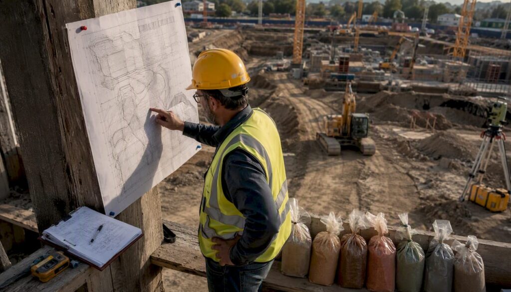
The primary geotechnical hazards on construction sites are slope failure, settlement, liquefaction, expansive and collapsible soils, trench cave-ins, erosion, sinkholes, bearing-capacity failure, and seismic ground failure. When any of these conditions are suspected, three actions take priority before investigation begins.
Immediate actions for site teams:
- Stop work in the affected zone and restrict access until a competent person has assessed the conditions.
- Preserve existing evidence: photograph tension cracks, record water levels, and secure any available subsurface reports or boring logs.
- Notify the designated competent person or a licensed geotechnical engineer, and implement temporary protective systems — shoring, benching, diversion ditches, or trench shields as conditions warrant.
OSHA’s 29 CFR 1926 Subpart P governs excavation safety on U.S. construction sites, including the prohibition under 29 CFR 1926.651(h) on entering water-accumulating excavations without protective systems and monitored water-removal equipment. The Federal Highway Administration (FHWA) further identifies landslides, liquefaction, rockfalls, subsidence, and erosion as persistent geohazards whose frequency and severity can increase with intense or prolonged rainfall.
Table of Contents
- What are the most common geotechnical hazards on construction sites?
- Why ignoring ground stability issues can cost you far more than the fix
- How to identify and assess geotechnical hazards: a step-by-step workflow
- What mitigation options are available, and how do you choose?
- U.S. safety requirements every construction team must follow
- When should you bring in a geotechnical engineer?
- Monitoring, inspection, and geotechnical asset management over the project lifecycle
- How agency frameworks and expert methodology support sound decisions
- Key Takeaways
- A practitioner’s perspective on geotechnical hazard management
- Stellar Structures brings geotechnical expertise to your project from day one
- Useful sources and references
What are the most common geotechnical hazards on construction sites?
Recognizing a hazard early, before it becomes a failure, is the single most cost-effective intervention available to a project team. The following hazards cover the conditions responsible for the majority of construction-related ground failures in the United States.
Slope failure and landslide
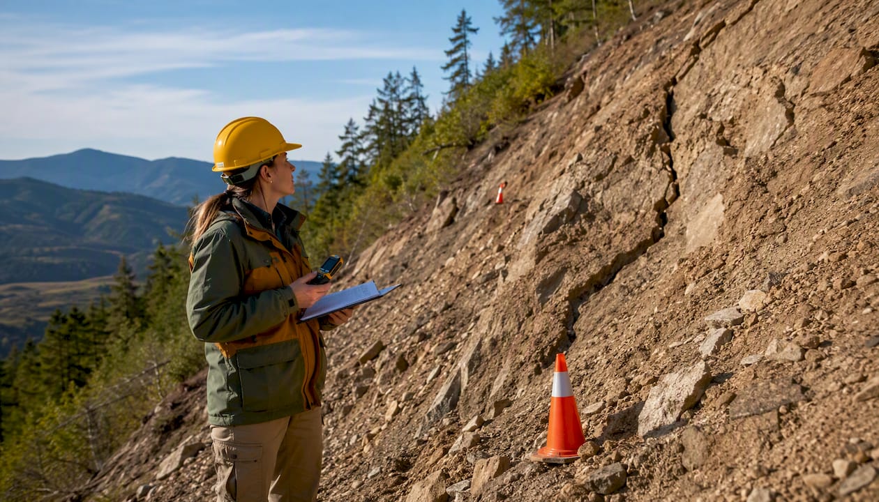
Occurs on cut slopes, fill embankments, and natural hillsides. Field indicators include new tension cracks running parallel to the crest, seepage emerging at the toe, and progressive bulging of the slope face. A slope failure can bury workers, destroy equipment, and trigger months of remediation.
Settlement and differential settlement
Affects structures founded on compressible clays, loose fills, or organic soils. Watch for cracking in adjacent pavements or structures, tilting of nearby utilities, and ponding water in previously level areas. Differential settlement, where one part of a foundation moves more than another, causes structural distress that is expensive to repair after the fact.
Liquefaction
Loose, saturated sandy soils lose shear strength during seismic shaking and behave like a dense fluid. Field precursors include sand boils after minor seismic events, lateral spreading at riverbanks, and a history of fill placement over former water bodies. Liquefaction can cause rapid, catastrophic foundation failure with little warning.
Expansive and collapsible soils
Expansive clays swell when wetted and shrink when dried, generating pressures that crack slabs and walls. Collapsible soils, common in arid regions, compress suddenly when saturated. Indicators include existing cracking in nearby structures, high plasticity index on lab reports, and a site history of irrigation or flooding.
Trench collapse and cave-ins
OSHA identifies excavation as one of the most hazardous construction operations. Bulging trench walls, tension cracks near the edge, and fissured or layered soils are warning signs that a trench face is approaching failure. Cave-ins kill workers with little or no warning.
Erosion and scour
Surface erosion strips topsoil and undermines slopes; scour at bridge piers and culverts removes foundation support. Indicators include rilling on exposed slopes, turbid runoff, and exposed aggregate at structure bases. Scour is a leading cause of bridge failure in the United States.
Sinkholes and karst
Dissolution of limestone, dolomite, or gypsum creates subsurface voids that can collapse suddenly. Surface depressions, circular cracks, and anomalous soft zones during drilling are field signs. Sinkhole collapse has caused fatalities and total structural losses on projects where karst geology was not adequately investigated.
Bearing-capacity failure
Occurs when applied loads exceed the soil’s capacity to support a foundation, resulting in sudden or progressive settlement and structural collapse. Soft, saturated clays and loose granular soils are most susceptible. Tilting structures, cracking at column bases, and heave of adjacent ground are observable indicators.
Rockfall and rock instability
Relevant on cut slopes in jointed or weathered rock. Loose blocks, overhanging ledges, and water-filled discontinuities signal elevated risk. Rockfall events are fast and offer no time for evacuation once initiated.
Seismic-induced ground failure
Beyond liquefaction, earthquakes trigger slope failures, lateral spreading, and fault rupture. Sites within USGS seismic hazard zones, near active faults, or underlain by soft bay mud carry elevated risk that must be addressed in design.
Pro Tip: Keep a simple field log on every site visit: note any new cracking, water seepage, or ground movement with a date, location, and photograph. This record becomes critical evidence for a geotechnical engineer and for OSHA compliance documentation.
Why ignoring ground stability issues can cost you far more than the fix
The human cost of inadequate geotechnical attention is well documented. Research published in PMC found that approximately 54.3% of examined geotechnical site accidents resulted in fatalities; among these, 28.3% were due to fractures and 25.1% due to asphyxia. These are not near-miss statistics; they represent workers who did not return home.
Beyond fatalities, ground failures generate contractual disputes, regulatory enforcement actions, and project delays that can run months. The competent person designated under OSHA Subpart P carries personal legal exposure when protective systems are absent or inadequate. Owners and general contractors face liability when geotechnical deliverables are omitted from the project scope or when investigation findings are not acted upon before construction begins.
The cost-benefit case for early geotechnical investment is straightforward: a geotechnical investigation conducted before design is a fraction of the cost of redesigning a foundation mid-construction or remediating a slope failure after the fact.
How to identify and assess geotechnical hazards: a step-by-step workflow
A defensible site investigation follows a structured sequence from desktop review through laboratory analysis. Project teams that understand this sequence can scope investigations more accurately, ask the right questions of their consultants, and interpret deliverables with confidence.
- Desktop data review. Compile existing geology maps, USGS hazard data, FHWA geohazard resources, prior boring logs, and aerial photography. Identify mapped faults, flood zones, karst areas, and historic fill extents before setting foot on site.
- Site reconnaissance and mapping. Walk the site systematically. Record slope geometry, drainage patterns, existing structures, signs of past movement, and any anomalous surface features. Photograph everything.
- Focused borings and cone penetration tests (CPTs). Borings provide soil samples and allow standard penetration tests (SPT); CPTs provide continuous stratigraphic profiles with minimal disturbance. Spacing and depth depend on project type — concentrated building footprints typically require one boring per major load-bearing element; linear projects require targeted investigation strategies because dense sampling across an entire route is rarely feasible.
- Groundwater monitoring. Install standpipe piezometers or vibrating-wire piezometers in borings to establish seasonal groundwater levels. Groundwater depth directly affects excavation stability, liquefaction susceptibility, and foundation design.
- Laboratory testing. Select tests based on the hazards identified in steps 1–3.
- Stability, liquefaction, and settlement analyses. Apply the field and lab data to quantitative analyses. Slope stability uses limit-equilibrium or finite-element methods; liquefaction screening uses SPT or CPT-based simplified procedures; settlement uses consolidation test results.
- Geotechnical report with design parameters. The engineer synthesizes findings into a report that includes soil profiles, design parameters, recommended factors of safety, foundation options, and earthwork specifications.
- Update during construction. When probe borings or excavation exposures reveal conditions that differ from the baseline, update the geotechnical model and notify the design team promptly. Numerical analysis tools such as PLAXIS allow rapid re-evaluation when subsurface conditions change.
Recommended geotechnical tests
| Test | Purpose | When to Use |
|---|---|---|
| Standard Penetration Test (SPT) | Soil density, stratigraphy, liquefaction screening | Most projects; required for seismic sites |
| Cone Penetration Test (CPT) | Continuous stratigraphy, strength, pore pressure | Soft soils, sites needing high resolution |
| Atterberg Limits | Plasticity, expansive/collapsible soil classification | Cohesive soils, pavement subgrades |
| Grain Size Analysis | Soil classification, drainage, liquefaction susceptibility | All projects |
| Consolidation Test | Settlement magnitude and rate | Compressible clays, soft ground |
| Triaxial Shear Test | Shear strength parameters for stability analysis | Slopes, retaining walls, deep foundations |
| Permeability Test | Groundwater flow, dewatering design | Excavations, dam/levee projects |
| Bulk Sampling | Material characterization for fill or stabilization | Earthwork-heavy projects |
What mitigation options are available, and how do you choose?
Matching the right mitigation method to the identified hazard requires understanding both the technical mechanism and the project constraints. The table below maps common methods to their typical applications.
| Mitigation Method | Typical Use Case | Relative Cost Impact | Key Consideration |
|---|---|---|---|
| Regrading and slope reshaping | Overly steep cut or fill slopes | Low to moderate | Requires adequate right-of-way |
| Retaining structures (walls, soldier piles) | Constrained sites, deep cuts | Moderate to high | Permanent; needs drainage design |
| Ground improvement (compaction, grouting, stone columns) | Weak soils, liquefaction risk, settlement control | Moderate | Verify with post-treatment testing |
| Deep foundations (driven piles, drilled shafts) | Poor near-surface soils, heavy loads | High | Bypasses problem soils entirely |
| Dewatering and groundwater control | Water-bearing excavations | Moderate | Ongoing cost during construction |
| Shoring and trench shields | Temporary excavation support | Low to moderate | Must comply with OSHA Subpart P |
| Chemical stabilization (lime, cement) | Expansive or weak subgrades | Low to moderate | Effective for pavement subgrades |
| Rock bolting and shotcrete | Jointed rock slopes, tunnel portals | Moderate to high | Requires rock mechanics input |
| Drainage and erosion control | Surface erosion, slope seepage | Low | Often first line of defense |
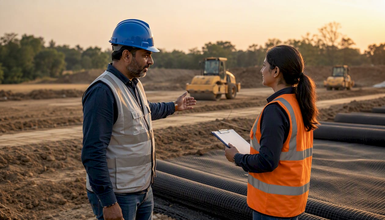
FHWA’s Ground Modification Methods manual documents over 50 ground modification technologies and provides a 12-step selection framework. For initial screening, the GeoTechTools catalog allows practitioners to shortlist methods by soil type, project constraint, and performance objective before committing to a detailed design.
Ground improvement becomes more economical than deep foundations when the weak layer is shallow and the treatment area is large. Conversely, when poor soils extend to significant depth or when load concentrations are high, deep foundations typically offer a more reliable solution at comparable cost.
Pro Tip: Sequence temporary measures before permanent works. Install shoring before excavating, complete dewatering before placing concrete, and avoid loading freshly placed fills until consolidation is verified. Premature loading is a recurring cause of embankment failures that proper staging would have prevented.
U.S. safety requirements every construction team must follow
OSHA’s 29 CFR 1926 Subpart P establishes the legal baseline for excavation safety on U.S. construction sites. Non-compliance is not a paperwork issue; it is a criminal and civil liability exposure.
Site compliance checklist for geotechnical work:
- Competent person designation. A competent person must be identified before excavation begins, must be capable of classifying soils, and must have authority to stop work.
- Soil classification. Classify soils as Type A, B, or C per Appendix B of Subpart P before selecting a protective system.
- Protective systems. Select sloping, benching, shoring, or trench shields based on soil class and excavation geometry. Sloping angles and benching configurations are specified in Subpart P Appendices B and C.
- Water control. Under 29 CFR 1926.651(h), workers may not enter an excavation where water is accumulating unless a competent person has implemented special support or shield systems and water-removal equipment is monitored continuously. Diversion ditches or dikes must be used where surface water could enter.
- Daily pre-shift inspections. The competent person must inspect excavations before each shift, after rainstorms, and after any event that could have changed conditions.
- Confined-space considerations. Excavations deeper than 4 feet that may contain hazardous atmospheres require atmospheric testing and confined-space entry procedures.
- Emergency response plan. Establish rescue procedures, ensure rescue equipment is on-site, and confirm that workers know the emergency contact chain before excavation begins.
A practical “find and fix” workflow: if the pre-shift inspection reveals tension cracks near the trench edge, the competent person stops work, extends the slope angle or adds shoring, documents the change, and re-inspects before allowing re-entry. OSHA’s recommended practices treat this cycle of hazard identification and proactive correction as the foundation of an effective construction safety program.
When should you bring in a geotechnical engineer?
Certain project conditions require specialist geotechnical input before design decisions are made. Waiting until a problem appears in the field is consistently more expensive than commissioning an investigation at the outset.
Triggers for engaging a geotechnical engineer:
- Excavations deeper than 5 feet in any soil, or any depth in Type C soils.
- Slopes steeper than 1.5H:1V or slopes with evidence of prior movement.
- Sites within USGS moderate-to-high seismic hazard zones or near mapped active faults.
- Suspected karst, sinkholes, or dissolution features identified in desktop review.
- Soft, organic, or highly plastic soils identified during reconnaissance.
- Unknown groundwater conditions or sites adjacent to water bodies.
- Critical structures: bridges, retaining walls taller than 10 feet, buildings with basements.
- Any project where the owner or contractor has encountered unexpected ground conditions during excavation.
What a geotechnical engagement delivers:
- Site reconnaissance report and preliminary hazard assessment
- Borehole logs, CPT records, and field test data
- Laboratory test results with interpreted parameters
- Geotechnical report with soil profiles, design parameters, and foundation recommendations
- Recommended factors of safety for slopes, retaining structures, and foundations
- Earthwork and compaction specifications
- Construction QA/QC guidance and inspection requirements
- Monitoring plan for construction and post-construction phases
Factors of safety in standard U.S. practice reflect infrastructure criticality. Slope stability guidance establishes a minimum factor of safety of 1.25 for routine highway embankments, 1.30–1.50 for major structures such as bridge abutments and interstate embankments, and 1.50 for cut slopes in fine-grained soils susceptible to long-term strength loss. These numbers are not conservative padding; they reflect the probability of encountering conditions worse than the design assumption.
On timeline and cost: a preliminary investigation for a small urban lot typically takes two to four weeks from mobilization to draft report. A full investigation for a large or complex project, including laboratory testing and analysis, commonly requires six to twelve weeks. Costs scale with the number of borings, laboratory program scope, and analysis complexity. A small residential investigation is a fraction of the cost of a major infrastructure study, but both are negligible relative to the cost of a foundation failure or a regulatory stop-work order.
Understanding what a geotechnical report contains and how it feeds into structural and foundation design decisions helps owners and contractors use the document effectively rather than filing it without review.
Monitoring, inspection, and geotechnical asset management over the project lifecycle
Geotechnical risk does not end when construction is complete. Ground conditions continue to change with seasonal moisture cycles, adjacent construction, and long-term consolidation. A monitoring program established during construction provides the baseline needed to detect post-construction movement before it becomes a structural problem.
Instrumentation types and applications:
- Inclinometers: Measure lateral ground movement in slopes, retaining walls, and embankments. Most useful where slope failure or wall deflection is a design concern.
- Piezometers (standpipe and vibrating-wire): Monitor groundwater levels and pore pressures. Critical for dewatering verification, consolidation tracking, and slope stability.
- Settlement plates and extensometers: Track vertical movement of fills, embankments, and structures. Settlement plates are installed at the base of fills; extensometers measure movement across specific intervals.
- Survey control points: Surface monuments monitored by total station or GPS provide a cost-effective check on overall ground movement.
- Remote monitoring systems: Automated data loggers connected to vibrating-wire instruments allow real-time alerts when readings exceed threshold values, reducing the need for frequent manual readings on active sites.
Monitoring plan checklist:
- Establish baseline readings before construction activities begin.
- Define monitoring frequency: typically weekly during active excavation or filling, monthly during consolidation phases, and quarterly post-construction.
- Set threshold values for each instrument type, with defined alert and action levels.
- Assign clear roles: the geotechnical engineer interprets data; the contractor is responsible for instrument protection and data transmission.
- Retain all monitoring records for the project lifecycle; they are critical for dispute resolution and future investigations.
- Determine when monitoring can be discontinued, typically when readings have stabilized for at least two consecutive seasonal cycles.
The FHWA frames slopes, embankments, and earth-retaining structures as long-term assets under its Geotechnical Asset Management (GAM) framework. GAM integrates condition assessments into system-wide lifecycle plans, allowing agencies and owners to prioritize inspection and maintenance resources toward the highest-risk assets rather than applying uniform inspection intervals across an entire portfolio.
Pro Tip: For projects with multiple instrumented locations, assign a single geotechnical engineer to review all monitoring data. Fragmented review, where different people look at different instruments, misses the cross-instrument patterns that often signal developing failures.
How agency frameworks and expert methodology support sound decisions
Sound geotechnical decision-making on U.S. construction projects draws on a consistent set of agency frameworks and practitioner tools. Understanding where each resource fits helps project teams use them efficiently.
Authoritative sources for U.S. geotechnical practice:
- OSHA (osha.gov): — Establishes legal requirements for excavation safety, competent-person duties, and protective systems under 29 CFR 1926 Subpart P. The primary compliance reference for any U.S. construction site.
- FHWA Geohazards Manual: — Documents geohazard types, climate-driven risk factors, and asset-management approaches for transportation infrastructure. Directly applicable to linear projects and sites in areas with elevated landslide or erosion risk.
On contractual risk management: FHWA policy guidance highlights Differing Site Conditions (DSC) clauses and Geotechnical Baseline Reports (GBRs) as the most effective tools for allocating ground risk between owners and contractors. A GBR sets a clear contractual definition of expected ground conditions at the time of bidding, which reduces pricing contingencies and limits dispute volume when unexpected conditions are encountered. Including DSC language and preparing a GBR at procurement is standard practice on major U.S. infrastructure projects and is increasingly adopted on complex building projects as well.
Key Takeaways
Geotechnical hazards on construction sites require immediate field recognition, structured investigation, code-compliant protective systems, and specialist engineering input to manage safely and cost-effectively.
| Point | Details |
|---|---|
| Recognize hazards early | Field indicators such as tension cracks, sand boils, and bulging trench walls signal developing failures before they become emergencies. |
| Follow OSHA Subpart P | 29 CFR 1926 Subpart P mandates competent-person designation, soil classification, and protective systems for all U.S. excavations. |
| Commission a structured investigation | A desktop review, borings or CPTs, lab testing, and analysis sequence reduces unforeseen conditions and supports defensible design parameters. |
| Apply appropriate factors of safety | Standard U.S. practice requires FS 1.25–1.50 depending on structure criticality; these values must be documented in the geotechnical report. |
| Engage Stellar Structures early | Stellar Structures delivers geotechnical site investigations, design checks, and monitoring programs that integrate directly into construction sequences and authority submissions. |
A practitioner’s perspective on geotechnical hazard management
The projects that handle geotechnical risk well share a common characteristic: the geotechnical engineer is brought into the conversation before the design is fixed, not after the excavation has already started. When a site team flags an anomaly, whether a soft zone encountered during stripping, a tension crack appearing overnight, or unexpected water in a test pit, the sequence that follows determines whether the project recovers cleanly or compounds the problem.
The typical workflow from initial flag to handover runs as follows: the site team documents the condition and notifies the project engineer; temporary protective measures are implemented immediately (shoring, slope flattening, dewatering as appropriate); probe borings are advanced to characterize the extent of the anomaly; the geotechnical engineer reviews the new data and issues revised design parameters or recommendations; and the construction sequence is adapted before work resumes. Monitoring instruments are installed at the same time as the probe borings, so that baseline readings are established before the next phase of work loads the ground.
For construction managers preparing to engage a geotechnical consultant, the most useful package to assemble in advance includes: the site plan with existing structures and utilities marked, any available boring logs or previous geotechnical reports, a description of the proposed construction (excavation depths, foundation loads, slope geometry), and a clear account of any anomalies or concerns already observed on site. A consultant who receives this information at the first meeting can scope the investigation accurately and avoid the delays that come from incomplete project briefs.
The sequencing principle that applies across nearly every project type is this: temporary shoring before excavation, probe borings before adaptive design, and monitoring before handover. Skipping any step in that chain transfers risk forward, where it is always more expensive to address.
Stellar Structures brings geotechnical expertise to your project from day one
When a project faces ground stability issues, the difference between a controlled response and a costly failure often comes down to how quickly specialist geotechnical input is integrated into the construction sequence. Stellar Structures provides geotechnical site investigation, design checks, deep-excavation shoring design, monitoring programs, and geotechnical input for authority submissions, delivering coordinated technical support across the full project lifecycle.

Relevant services for projects with geotechnical exposure:
- Geotechnical site investigation scoping and coordination
- Civil and structural design checks for projects with foundation or slope risk
- Deep-excavation shoring design and value engineering
Before making contact, prepare a site drawing with existing structures and utilities marked, any available subsurface reports or boring logs, a description of proposed excavation depths and foundation loads, and a note of any ground anomalies already observed. This preparation allows Stellar Structures to scope an engagement accurately and mobilize without delay. Engage a geotechnical consultant before design is fixed, and the investigation cost becomes a design input rather than an emergency response.
Useful sources and references
The following primary sources underpin the guidance in this article. Each is the authoritative reference for its domain.
- OSHA 29 CFR 1926 Subpart P (Excavations) — The legal standard for U.S. excavation safety, covering competent-person requirements, soil classification, and protective systems. The compliance baseline for every U.S. construction site.
- FHWA Geohazards, Extreme Weather Events, and Climate Change Resilience Manual — Covers geohazard types, climate-driven risk factors, and Geotechnical Asset Management concepts for transportation infrastructure.
- FHWA Ground Modification Methods Reference Manual (NHI-16-028) — Documents over 50 ground modification technologies and the 12-step selection framework. The primary reference for mitigation method selection.
- PMC: Geotechnical Accident Fatality and Injury Analysis — Peer-reviewed analysis of fatality rates and causes in geotechnical site accidents. Source for the 54.3% fatality rate and fracture/asphyxia cause data.
- Buildberry: Construction Task Management Guide — Practical guidance on integrating geotechnical monitoring and reporting into project controls and construction task management workflows.
Recommended
- Geotechnical Site Investigation in Singapore:
- When You Need a Geotechnical Engineering Consultant – Stellar Structures
- How Geotechnical Reports Drive Design Decisions
- Singapore Foundation Engineering Guide 2025: Geotechnical design, cost, and structural systems