
A structural drawing is a technical blueprint that documents the load-bearing skeleton of a building, specifying the size, layout, material grades, and reinforcement of every structural element. These documents cover foundations, columns, beams, slabs, and connection details, forming the engineering basis for safe construction. Unlike a sketch or a concept plan, a structural drawing carries legal and technical weight. For property owners, aspiring builders, and anyone planning a renovation, understanding what these drawings contain and how to use them is the difference between a compliant build and a costly mistake.
What is a structural drawing and what does it include?
A structural drawing, also called a structural engineering drawing, is a set of technical documents prepared by a licensed structural engineer to define how a building resists gravity, wind, and other applied loads. The industry standard term is structural engineering drawing, though the shortened form is used interchangeably across construction sites and permit offices.
These drawings specify foundations, columns, beams, and slabs as discrete elements, each with defined dimensions, material grades, and connection requirements. A reinforced concrete beam, for example, will be shown with its cross-section dimensions, the number and diameter of reinforcing bars, and the concrete grade required. Nothing is left to interpretation on a properly prepared set.

The structural drawing notes also include critical construction requirements such as concrete curing times, welding standards, and soil bearing assumptions. These notes are not supplementary. Construction professionals treat them as legally binding technical requirements, and misinterpreting them risks non-compliance and structural failure.
Property owners often assume structural drawings are similar to architectural floor plans. They are not. Architectural drawings show room layouts, door positions, and finishes. Structural drawings show what holds the building up. Both are necessary, but they answer entirely different questions.
Types of structural drawings used in construction
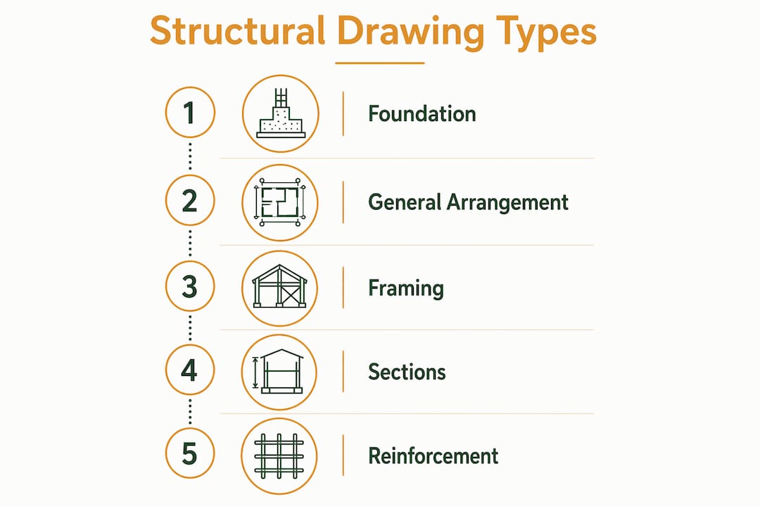
Standard structural drawing sets typically include five to seven distinct drawing types, each serving a specific purpose in documenting the building’s framework. Understanding each type helps property owners and builders know which document to consult at each stage of a project.
| Drawing Type | Primary Purpose | Key Content |
|---|---|---|
| Foundation Plan | Shows how the structure transfers loads to the ground | Footing sizes, pile layouts, ground beam dimensions |
| General Arrangement Drawing | Provides an overall structural layout | Column and wall grid, floor levels, key dimensions |
| Framing Plan | Details the floor and roof structural members | Beam spans, slab thickness, member sizes |
| Section Drawing | Shows vertical cuts through the structure | Floor-to-floor heights, wall construction, structural depth |
| Reinforcement Drawing | Specifies steel reinforcement in concrete elements | Bar sizes, spacing, cover, lap lengths |
| Connection Detail | Shows how structural members join together | Bolt patterns, weld specifications, bracket types |
| Steel Fabrication Drawing | Used by fabricators to manufacture steel members | Exact dimensions, hole positions, surface treatment |
Each drawing type addresses a specific trade or construction phase. Foundation plans guide the civil contractor during earthworks. Reinforcement drawings direct the steel fixer before concrete is poured. Steel fabrication drawings go directly to the workshop before a single piece of steel arrives on site. Together, these documents ensure that every contractor works from the same verified set of engineering decisions, reducing coordination errors and rework.
Pro Tip: When reviewing a drawing set for the first time, check that all drawing types are present and that their revision numbers match. A mismatched set, where the foundation plan is at Revision C but the reinforcement drawing is still at Revision A, is a common source of construction errors.
How to read structural drawings: a step-by-step approach
Reading structural drawings accurately requires a defined sequence. Skipping steps or jumping straight to dimensions is how errors enter a build. The professional workflow follows a consistent order that minimizes misinterpretation.
-
Check the title block and revision status. Every structural drawing features a title block in the lower right corner. It records the drawing number, revision letter, date, and the engineer’s signature. Always confirm you are working from the current revision before reading anything else. Superseded drawings on site are one of the most common causes of construction defects.
-
Read the general notes and legend first. The notes page defines abbreviations, material grades, and construction standards that apply to the entire drawing set. For instance, a note stating “All reinforcement to be Grade 500 MPa unless noted otherwise” changes how you read every reinforcement detail on every sheet.
-
Locate the grid reference system. Structural drawings use a grid intersection system of numbered columns and lettered rows to create a coordinate system for the building. Every element is referenced to a grid point, such as Column B3 or Beam B3 to C3. This system allows you to locate any element precisely on both the plan and section views.
-
Cross-reference plan views with section drawings. A plan view shows where elements are positioned horizontally. A section drawing shows how they are constructed vertically. Reading one without the other gives an incomplete picture. When a plan shows a beam marked “B1,” the corresponding section or detail drawing shows its full cross-section, reinforcement, and connection requirements.
-
Interpret reinforcement schedules carefully. Reinforcement schedules specify bar diameters ranging from 6mm to 57mm, concrete grades from 20 MPa to over 100 MPa, and steel yield strengths from 250 MPa to 500 MPa. These values directly determine structural performance under gravity, wind, and seismic loads. A bar diameter error of even one size can reduce a member’s load capacity significantly.
-
Never scale off a drawing to take measurements. Scaling off drawings to measure dimensions is a critical error. Drawings may not print to scale, or they may have been modified after the original scale was set. Always use the explicit dimensions printed on the drawing.
Pro Tip: If a dimension appears to conflict with what you see on the drawing, flag it with the engineer of record immediately. Do not resolve the discrepancy by measuring the paper. The engineer’s written dimension governs.
Structural drawings vs. architectural drawings: key differences
Structural and architectural drawings serve distinct purposes and are prepared by different professionals. Confusing them leads to gaps in project understanding and, in some cases, to unsafe construction decisions.
Architectural drawings are prepared by a registered architect and focus on the spatial and aesthetic qualities of a building. They define room layouts, ceiling heights, door and window positions, material finishes, and the overall design intent. An architectural drawing tells you what the building looks like and how people move through it.
Structural drawings are prepared by a licensed structural engineer and focus entirely on strength and stability. They define how the building stands up under load. Where an architectural drawing shows a wall as a line with a finish material, a structural drawing shows whether that wall is load-bearing, what its construction is, and how it connects to the floor and roof above.
The key differences between the two drawing types are as follows:
- Author: Architect vs. structural engineer
- Primary focus: Aesthetics and spatial layout vs. load resistance and structural integrity
- Content: Room dimensions, finishes, and openings vs. member sizes, material grades, and reinforcement
- Regulatory use: Required for planning and building permits vs. required for structural approval and BCA compliance in Singapore
- Construction use: Guides finishes, partitions, and fit-out trades vs. guides civil, structural, and steel trades
Both drawing types are submitted together for authority approvals. In Singapore, agencies such as the Building and Construction Authority (BCA) and the Urban Redevelopment Authority (URA) require both sets before a permit is issued. Neither set alone is sufficient for a compliant build. For a deeper look at how civil engineering inputs shape architectural decisions, the article on civil engineering and architectural design explains the coordination process in detail.
Why structural drawings matter for property owners and builders
Understanding structural drawings is critical for safety, durability, and coordination across all trades on a construction project. For property owners, the practical stakes are direct: a misread drawing or an ignored note can result in a code violation, a failed inspection, or a structural defect that costs far more to fix than the original build.
The most common risk for property owners arises during renovations. Removing or modifying a wall, adding an opening, or changing floor loading without consulting the structural drawings can compromise a load-bearing element. Property owners and builders frequently treat structural drawings as DIY guides, but they are complex engineering documents that require technical knowledge to interpret correctly. Engaging a structural engineer for renovation work is not optional when load-bearing elements are involved.
Structural drawings also serve as the primary reference during site inspections. When a building inspector or a structural engineer visits a site, they compare the physical construction against the approved drawings. Deviations, even minor ones, can trigger stop-work orders or require costly remediation. Keeping the approved drawing set on site and ensuring all contractors work from the current revision is a basic but frequently neglected practice.
“Construction professionals use structural drawing notes as legally binding technical requirements. Misinterpretation risks non-compliance and structural failure.” — Smart Construction Guide
For aspiring builders, structural drawings are also a communication tool. When you can read a drawing well enough to ask specific questions, such as why a particular beam size was chosen or what the design load assumption is for a floor, you engage more productively with your engineer and contractor. That level of engagement catches errors earlier and keeps projects on schedule.
Pro Tip: Before any renovation that touches walls, floors, or the roof structure, request the original approved structural drawings from your engineer or the relevant authority. In Singapore, approved drawings for most buildings are held by BCA and can be retrieved through the relevant submission records.
Key takeaways
Structural drawings are the definitive engineering record of a building’s load-bearing framework, and every property owner or builder who engages with construction work should know how to use them.
| Point | Details |
|---|---|
| Core definition | A structural drawing documents load-bearing elements including foundations, columns, beams, and slabs with precise material and reinforcement specifications. |
| Drawing types | Standard sets include five to seven types, from foundation plans to steel fabrication drawings, each serving a specific construction phase. |
| Reading sequence | Always check revision status, read general notes first, use grid references, and cross-reference plans with sections before interpreting dimensions. |
| Structural vs. architectural | Structural drawings address load resistance; architectural drawings address layout and aesthetics. Both are required for authority approval. |
| Renovation risk | Modifying load-bearing elements without consulting structural drawings risks code violations, structural failure, and costly remediation. |
Why non-engineers should take structural drawings seriously
Most property owners I work with assume structural drawings are the engineer’s problem. They sign off on the architectural plans, approve the finishes, and leave the structural set to the contractor. That approach works until something goes wrong, and by then the options are expensive.
What I have observed over years of working on projects across residential, commercial, and industrial sectors is that the clients who engage with structural drawings, even at a basic level, consistently have fewer surprises during construction. They ask better questions. They catch discrepancies earlier. They understand why certain design decisions cost more and why cutting corners on a specific detail is not worth the saving.
You do not need to be an engineer to use structural drawings effectively. You need to know what revision you are looking at, what the general notes say about material grades, and which elements are load-bearing. That knowledge alone puts you in a position to have an informed conversation with your engineer and contractor rather than simply trusting that everything is in order.
The DNA of a building’s framework is recorded in these documents. Treating them as background paperwork is a missed opportunity. Treat them as the primary technical reference for your project, and you will make better decisions at every stage.
— Aman
How Stellar Structures supports your structural drawing needs

Stellar Structures provides civil and structural design checks for property owners, developers, and contractors who need confidence that their structural drawings meet Singapore’s engineering and regulatory standards. The team reviews drawing sets for compliance with BCA requirements, checks reinforcement details, and identifies coordination issues before they become site problems. Whether you are planning a new build, a renovation, or need a second opinion on an existing set of drawings, Stellar Structures delivers precise, code-compliant engineering support. Reach out to discuss your project requirements and get the technical clarity your build deserves.
FAQ
What does a structural drawing show?
A structural drawing shows the load-bearing elements of a building, including foundations, columns, beams, slabs, and connections, with precise dimensions, material grades, and reinforcement specifications. It does not show finishes, room layouts, or aesthetic details.
How are structural drawings different from floor plans?
Floor plans are architectural documents showing room layouts, door positions, and spatial dimensions. Structural drawings show how the building’s framework resists loads, specifying member sizes, concrete grades, and steel reinforcement.
Do property owners need to understand structural drawings?
Property owners benefit significantly from a working understanding of structural drawings, particularly during renovations involving load-bearing walls or structural alterations. Misinterpreting or ignoring these documents can result in code violations or structural compromise.
What are the main types of structural drawings?
The main types include foundation plans, general arrangement drawings, framing plans, section drawings, reinforcement drawings, connection details, and steel fabrication drawings. Each type addresses a specific phase or trade in the construction process.
Can you scale measurements off a structural drawing?
No. Scaling off a structural drawing to take measurements is unreliable because drawings may not print to scale or may have been modified after the original scale was set. Always use the explicit dimensions printed on the drawing.
Recommended
- What Is an As-Built Drawing? A Professional Guide
- Hiring a Structural Engineer for Renovation in Singapore
- Why Engage a Structural Engineer for Your Landed Home
- What Is Structural Engineering: A Beginner’s Guide – Stellar Structures