




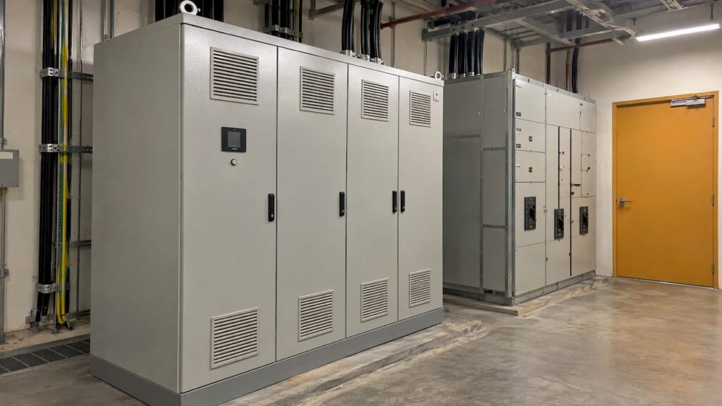
Power factor correction is the installation of equipment, most often capacitor banks, that supplies reactive power locally so that the current drawn from the supply falls for the same useful load. For a building owner, developer or contractor in Singapore, the result is a lower apparent demand in kVA, lower cable and transformer losses and spare capacity on the existing incomer. The correction is only as good as its design: sizing, location and harmonic assessment decide whether it performs reliably, and these belong in the M&E design stage, not as an afterthought on site.
TL;DR
- Power factor is the ratio of useful power (kW) to apparent power (kVA). Unity (1.0) is ideal, and typical corrected values fall between 0.92 and 0.95.
- In Singapore, the supply connection process assumes a power factor of 0.85, and induction motors typically run near 0.85 uncorrected, so correction is a standard design item for motor-heavy and mixed-use loads.
- Capacitor banks are the usual method: fixed banks for steady base loads, automatic banks for loads that vary through the day.
- Where variable speed drives, UPS systems or LED drivers share the busbar, harmonics must be assessed first, and detuned (reactor-connected) capacitors are often required.
- Correction should be specified by the M&E engineer during design, so that the equipment, its connection point and its protection are coordinated with the rest of the installation.
Table of Contents
- What power factor measures, and what 0.80 or 0.95 means
- Why it matters in a Singapore building
- How capacitor banks correct power factor
- Harmonics: the design risk that decides the equipment
- Other correction methods
- When new loads change the picture
- A practical sequence for owners and developers
- Perspective
- How Stellar Structures supports the design and approvals
- FAQ
- Sources
What power factor measures, and what 0.80 or 0.95 means
Electrical equipment with coils and windings, such as motors, transformers and chillers, draws two kinds of current. One part produces useful work (measured in kW). The other builds the magnetic fields the equipment needs (reactive power, in kVAr). The supply must carry both, and the vector sum is the apparent power in kVA.
The Institution of Engineering and Technology defines power factor as the ratio of true power (kW) to apparent power (kVA), with unity as the ideal. A load at 0.8 causes much higher losses in the supply system and a higher bill for the consumer, and a corrected installation typically lands at 0.92 to 0.95.
The practical meaning of a given value is easiest to see in the kVA required for the same kW:
| Power factor | Apparent power needed for 100 kW | Relative current |
|---|---|---|
| 0.70 | 142 kVA | Highest |
| 0.95 | 105 kVA | About 26% lower |
These figures come from the US Department of Energy’s fact sheet on reducing power factor cost, which shows that a capacitor of about 67 kVAR on a 100 kW inductive load at 0.70 brings the power factor to 0.95 and cuts current by 26%. Eaton’s plant engineer guide reaches the same 142 kVA to 105 kVA reduction, a 35% cut in apparent power, and notes that 95% gives the maximum benefit in practical use. Beyond that point, each extra increment of capacitance buys little and raises the risk of overcorrection.
Why it matters in a Singapore building
A low power factor does not waste useful energy directly, but it forces the installation to carry more current than the work requires. The consequences are physical and financial:
- Higher losses. Greater current heats cables, busbars and transformers.
- Reduced capacity. The US Department of Energy notes that low power factor reduces distribution capacity by increasing current flow and causing voltage drops, and that excessive voltage drop can overheat motors and shorten their life.
- Charges and penalties. The National Environment Agency’s MDS Reference Manual 2018 records that induction motors typically operate at about 0.85, and that low power factor leads to higher line losses and potential penalty charges from the utility.
- Headroom for growth. Released capacity can allow added load, such as new chillers or EV chargers, without upsizing the incoming supply.
The 0.85 reference in Singapore
SP Group’s handbook on applying for an electricity connection states that, when contracted capacity is assessed, the power factor is based on 0.85. Separately, the Energy Market Authority’s Transmission Code requires connected persons taking supply at high voltage to implement correction where the transmission licensee deems it necessary, to maintain a power factor of no less than 0.85. Designers therefore treat 0.85 as the floor and commonly target 0.92 to 0.95, in line with the range the IET describes. The exact obligation depends on the supply voltage and the licence arrangements for the premises, which the M&E engineer confirms against the current documents at design stage.
For energy efficiency more broadly, SS 530 (the Singapore Standard code of practice for energy efficiency of building services and equipment) sets minimum requirements for new installations and replacements, including motor drives and distribution transformers. Correction equipment is designed alongside these items.
How capacitor banks correct power factor
Inductive loads draw lagging reactive current. A capacitor draws leading reactive current, so a capacitor connected in parallel with the load supplies the reactive power locally instead of drawing it from the grid through the cables. The NEA manual describes the same principle: capacitors installed in parallel with the load reduce reactive power.
A worked sizing example
Consider a factory with a 200 kW average demand at a power factor of 0.85. The reactive power is 200 × tan(arccos 0.85), about 124 kVAr. To reach 0.95, the reactive power must fall to 200 × tan(arccos 0.95), about 66 kVAr. The capacitor bank therefore needs to supply roughly 58 kVAr. Apparent power drops from about 235 kVA to about 211 kVA. This is the engineer’s own arithmetic, shown to illustrate the method; a real design uses measured load profiles, not a single average.
Fixed versus automatic banks
| Type | How it works | Suited to |
|---|---|---|
| Fixed capacitor | Connected continuously, sized for the base load | Steady loads such as a single large motor or constant base demand |
| Automatic (APFC) bank | A controller switches capacitor steps in and out according to measured reactive demand | Buildings whose load varies through the day, such as mixed-use developments and industrial plants |
A fixed bank on a varying load will overcorrect at low demand, which can push the power factor leading and raise voltage. The Electrical Contractors’ Association advises that correction at the meter position needs automatic control to avoid overcorrection at low loads, which is why most commercial installations use automatic banks.
Where to locate the equipment
There are three common positions: at the main incomer or meter position (central correction), at distribution boards or motor control centres (group correction), and at the individual large motor (local correction). Central correction is simpler, with one bank to install and maintain. Local correction relieves the cables between the board and the motor but multiplies the number of units. The ECA notes that placing equipment at the meter allows advantage to be taken of leading power factor equipment, reducing the installed kVAr. Provision for a correction connection point, such as a spare way in the relevant board, is best settled when the single-line diagram is drawn, because retrofitting space in a crowded switchroom is costly.

Harmonics: the design risk that decides the equipment
Capacitors are linear loads and do not themselves generate harmonics. The risk is resonance. SP Group’s guide Collaborating Towards Power Quality explains that capacitors may form a parallel resonance with the supply inductance, that more capacitance lowers the resonant frequency, and that a high-impedance point combined with non-linear loads can produce much higher voltage distortion.
Modern Singapore buildings contain many non-linear loads: variable speed drives on chillers and pumps, UPS systems, LED drivers and, increasingly, EV chargers. Electronicon’s technical guide gives practical rules:
- Detuned (reactor-connected) capacitors are recommended wherever non-linear loads exceed 10% of the rated transformer power.
- Detuned and non-detuned capacitors must never be combined in the same network.
- A detuned capacitor improves power factor while preventing amplification of harmonic currents and voltages through resonance.
- A mains analysis, including harmonic content, should precede design wherever possible.
SP Group’s guide adds that where correction would cause resonance problems, it should be implemented as harmonic filters that provide both power factor correction and harmonic control, and active filters may also be considered.
The point for owners is that a capacitor bank chosen by kVAr alone can become the cause of nuisance trips, overheated equipment and data corruption. The specification must name the detuning factor, the capacitor rating for the harmonic environment, the step arrangement and the protection. Our own note for facility teams on monitoring power quality in buildings sets out a phased approach to measurement that feeds directly into this design decision.
Other correction methods
Capacitor banks are not the only route. Where the load permits:
- Variable speed drives with active front ends draw close to unity power factor while controlling motor speed, so they correct at source.
- Retrofitting drives to constant-speed fans, pumps and compressors improves power factor and reduces energy use, because power falls steeply with speed.
- Harmonic filters combine correction and harmonic control on difficult busbars.
The choice depends on the load mix, the available space and the budget, and it is a design judgment rather than a catalogue selection.
When new loads change the picture
Power factor is not fixed at handover. Adding chillers, lifts or EV charging points shifts the load profile and the harmonic content. Management corporations planning EV charging should read the practical guide to EV charging for Singapore MCSTs alongside an assessment of the existing incomer, since the added demand and its power electronics affect both capacity and power quality. Likewise, solar installations on high-rise roofs bring inverters onto the network; our note on approvals for rooftop solar photovoltaic installations describes the authority side of such projects.
A practical sequence for owners and developers
- Measure. Record kW, kVA, kVAr and harmonic distortion at the main incomer over a representative period, covering peak and low-load conditions. Measuring only at peak will oversize the bank.
- Set the target. Take the supply requirement as the floor and design for the 0.92 to 0.95 range, avoiding any leading power factor at light load.
- Choose the type. Fixed for steady loads, automatic for varying loads, detuned or filtered where harmonic-generating loads are significant.
- Size and select. Specify the total kVAr, the number of steps, the detuning reactors and the protection. Capacitor standards such as IEC 60831 and IEC 60931 require, for instance, that capacitors tolerate a continuous current up to 30% above rated current to allow for voltage harmonics.
- Locate and provide space. Reserve switchroom space, ventilation and a dedicated connection point.
- Coordinate approvals. The correction equipment forms part of the electrical installation, which is documented in the design and submission package for the project and licensed electrical work.
- Verify after commissioning. Compare power factor and harmonic readings against the design target at several load conditions, and keep the data for maintenance.
Perspective
Power factor correction is routinely treated as a purchase of capacitors. In our experience of the design side of building projects, it is better treated as one part of the electrical design: the load schedule, the single-line diagram, the harmonic environment and the space allocation all determine whether the equipment performs.
Our M&E engineering design service and our authority submission work sit within the same team, led by a Professional Engineer with decades of experience in Singapore infrastructure. That allows the correction scheme to be settled together with the structural, architectural and approval requirements of the project, so that switchroom space, loading and documentation are resolved before construction, not during it.
For owners of landed homes undertaking additions and alterations, developers of mixed-use or industrial sites, and contractors under design-and-build contracts, the useful question is not which bank to buy but what the installation will look like in five years, with the loads it will then carry.
Aman
How Stellar Structures supports the design and approvals
Stellar Structures provides mechanical and electrical engineering design, architectural and interior design, and authority submissions across BCA, URA, HDB, JTC, SCDF, PUB, LTA, NEA and NParks for residential, commercial, industrial and infrastructure projects in Singapore. Where a project includes new or expanded electrical systems, the M&E design and the submission package can be prepared together. Details of each service are on the services page, and the team can be contacted through the Stellar Structures site to discuss a project.

FAQ
What is a good power factor target for a commercial or industrial building?
A corrected installation typically sits between 0.92 and 0.95, according to the IET. Going beyond 0.95 yields diminishing returns and increases the chance of overcorrection at low load. The supply reference in Singapore is 0.85, so a design target above that provides a margin.
What does a power factor of 80% mean?
It means that 80% of the apparent power drawn is doing useful work, and 20% is reactive. The installation must be sized and cabled to carry the full kVA, so losses are higher and capacity is used up. At 0.8, a 100 kW load needs 125 kVA, compared with about 105 kVA at 0.95.
Do capacitors always improve power factor safely?
Capacitors correct reactive power, but they can resonate with the supply inductance when non-linear loads such as drives or UPS systems are present. SP Group’s guidance recommends harmonic filters where resonance is a risk. A harmonic assessment before design avoids the problem.
Is a fixed or automatic capacitor bank better?
Fixed banks suit stable base loads. Automatic banks switch steps according to demand and are the usual choice for loads that vary through the day, because they avoid overcorrection at light load.
Sources
- Institution of Engineering and Technology: Power factor correction
- US Department of Energy: Reducing Power Factor Cost
- Eaton: Power factor correction, a guide for the plant engineer
- NEA: MDS Reference Manual 2018
- SP Group: How to Apply for Electricity Connection
- Energy Market Authority: Transmission Code
- Singapore Standard SS 530 code of practice
- ECA: Power Factor Correction
- SP Group: Collaborating Towards Power Quality
- Electronicon: Key components for power factor correction in 50 Hz mains
- ABB: Technical Application Paper No. 8, Power factor correction