




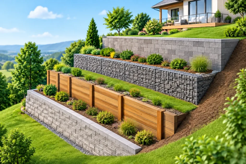
A retaining wall is rarely just a wall. It is part of a soil-support system that must manage ground pressure, water movement, adjacent structures, construction access, and authority requirements. The best retaining solutions are therefore not selected by appearance or initial wall cost alone. They are selected after the site conditions, required retained height, loading, drainage path, and approval route are understood.
For a homeowner, developer, contractor, or facility operator, the right choice can prevent expensive movement, water damage, boundary disputes, and redesign during construction. For projects involving basements, additions, slope changes, driveways, terraces, or constrained side yards, early engineering input is usually far less costly than correcting a wall after it has been built.
What Determines the Best Retaining Solutions?
Retaining systems resist lateral earth pressure. That pressure changes significantly with soil type, groundwater, slope geometry, and loads near the top of the wall. A low landscape wall holding back dry, compact granular fill is a different engineering problem from a wall beside a driveway, building foundation, public sidewalk, or swimming pool.
The starting point should be a site assessment. This may include a topographic survey, review of existing drawings, trial pits, geotechnical information, and an inspection of drainage conditions. If the site is near a property line or an existing structure, the design team also needs to establish where foundations, utilities, and neighboring improvements are located.
Three questions drive most decisions. First, how high is the retained soil, including any stepped portions? Second, what surcharge loads act behind the wall, such as vehicles, stored materials, building footings, or construction equipment? Third, where will water go during heavy rainfall and after irrigation? A wall can be structurally adequate on paper yet perform poorly when drainage is omitted or blocked.
Local requirements also matter. Height thresholds, setbacks, drainage discharge rules, excavation controls, and professional design requirements vary by jurisdiction. A proposed wall may trigger permits even when it appears to be a straightforward exterior improvement. Where excavation affects neighboring land or existing foundations, temporary works and monitoring may be required as well.
Common Retaining Systems and Their Best Uses
Reinforced concrete cantilever walls
Cast-in-place reinforced concrete walls are a common solution where durability, limited footprint, and predictable structural performance are priorities. The wall stem and base slab work together to resist overturning, sliding, and bearing pressure. This system can be shaped to follow changes in level and integrated with stairs, boundary walls, ramps, planters, or building works.
It is often suitable for medium-height to high retaining conditions, especially where vehicles or structures are near the wall. The trade-off is that concrete walls need competent foundation preparation, reinforcement detailing, formwork, curing, waterproofing where applicable, and a designed drainage system. They may also require more time and site coordination than modular alternatives.
Segmental concrete block walls
Segmental retaining walls use interlocking concrete blocks, usually with compacted granular backfill and geogrid reinforcement for taller applications. They can provide a practical finish for landscape works, residential grade changes, and terraces. Their modular construction can be efficient where access permits material delivery and staged installation.
These walls are not simply stacked blocks. Performance depends on base preparation, batter, drainage aggregate, compaction quality, geogrid length, and the soil behind the reinforced zone. A wall that looks sound at completion can bulge or settle if the contractor places backfill in thick lifts or fails to provide drainage outlets. For walls carrying significant surcharge loads, engineered design is essential.
Gravity walls and gabion walls
Gravity walls rely primarily on mass to resist soil pressure. They may be constructed from concrete, stone, precast units, or wire baskets filled with rock. Gabion walls are particularly useful where a permeable system is beneficial and a more natural, textured appearance is acceptable.
Their main advantage is drainage. Water can pass through the rock-filled face rather than build up behind a solid barrier. However, they require space because their base is typically wider than a reinforced concrete wall. Wire basket quality, rock size, corrosion exposure, settlement, and vegetation maintenance all require consideration. Gabions are not automatically appropriate for every boundary or high-load condition.
Soldier pile and lagging systems
Where a site is tight, excavation is deep, or an existing structure is close to the proposed cut, soldier piles and lagging may be appropriate. Steel or reinforced concrete piles are installed at intervals, with timber, precast concrete, or shotcrete lagging spanning between them. Tiebacks, internal bracing, or other support measures may be introduced for greater depths and loads.
This approach is commonly associated with basement excavation, commercial redevelopment, and constrained urban sites. It requires careful sequencing and inspection because ground movement during excavation can affect adjacent buildings, roads, and buried services. The system is highly capable, but it is generally not the lowest-cost answer for a modest garden level change.
Reinforced soil slopes
Not every level change needs a vertical wall. Where land is available, a reinforced soil slope with geogrid layers can be a cost-effective alternative. The face may use vegetation, erosion-control matting, blocks, or wrapped geotextile, depending on the slope angle and project requirements.
This solution can reduce the cost and complexity of a tall vertical structure, but it requires a wider footprint. It may not be viable near boundaries, buildings, utilities, or narrow access routes. Long-term erosion control and landscape maintenance should be planned from the outset.
Drainage Is Part of the Structural Design
Most avoidable retaining wall failures involve water. Saturated soil is heavier, drainage pressure increases behind the wall, and uncontrolled runoff can erode the footing or backfill. A proper design considers both surface water and subsurface water.
Typical measures include free-draining granular backfill, filter fabric to prevent fines from clogging the drainage layer, perforated collector pipes, outlets to an approved discharge point, and a finished ground profile that directs surface water away from the wall. Weep holes may help in certain wall types, but they are not a substitute for a complete drainage strategy.
Drainage must remain maintainable. Outlet locations should not be buried by later landscaping, paving, or fill. If a wall retains soil beside a basement or occupied space, waterproofing and drainage requirements need to be coordinated with the building envelope design, not decided after concrete has been poured.
Design for the Loads That Will Actually Be There
A retaining wall should be designed for current and foreseeable site use. A common error is treating a future driveway, extension, fence, or pool deck as an afterthought. Even a heavy fence can introduce wind-related load, while a vehicle near the wall can materially increase lateral pressure.
The design team should also review seismic conditions where applicable, expansive or weak soils, flood exposure, tree roots, utility corridors, and construction staging. On sloping properties, water flowing from higher ground can be more influential than the visible retained height alone.
A professional engineer can assess wall stability against overturning, sliding, bearing failure, and global slope failure. For deeper excavation or challenging ground, geotechnical input may be needed to determine soil parameters, groundwater assumptions, pile capacity, and temporary support requirements. This level of work may seem extensive for a small project, but it becomes necessary quickly when the consequences of movement are high.
Coordination Before Construction Saves Time on Site
Retaining work often intersects with architecture, civil drainage, structural design, and regulatory submissions. The wall location may affect setbacks, usable floor area, landscape planning, accessibility, or fire access. It may also require coordination with utility providers and local building authorities before excavation begins.
The construction package should clearly show wall sections, foundations, reinforcement or geogrid details, drainage, finished grades, waterproofing, construction joints, and any inspection hold points. Where existing structures are nearby, pre-construction condition surveys and movement monitoring may be appropriate.
Stellar Structures approaches retaining works as part of the wider site and approval problem, not as an isolated masonry item. That coordination is particularly useful when a grade change is connected to an addition, basement, driveway, boundary improvement, or redevelopment project.
Choosing a Solution That Can Be Built and Maintained
The most suitable retaining system balances structural need with site access, appearance, construction duration, budget, and long-term maintenance. A small landscaped terrace may suit a segmental wall or gravity system. A tight boundary beside a building may require reinforced concrete or a piled support system. A broad site with room to spread out may benefit from a reinforced slope rather than a tall wall.
Do not commit to a wall type based only on a product brochure or a contractor’s preferred method. Establish the ground conditions, drainage route, loads, approvals, and construction constraints first. A retaining solution that is properly designed, documented, and inspected gives the project team a clearer path from excavation to final grade – and gives the owner a structure that remains dependable long after the landscaping is complete.