




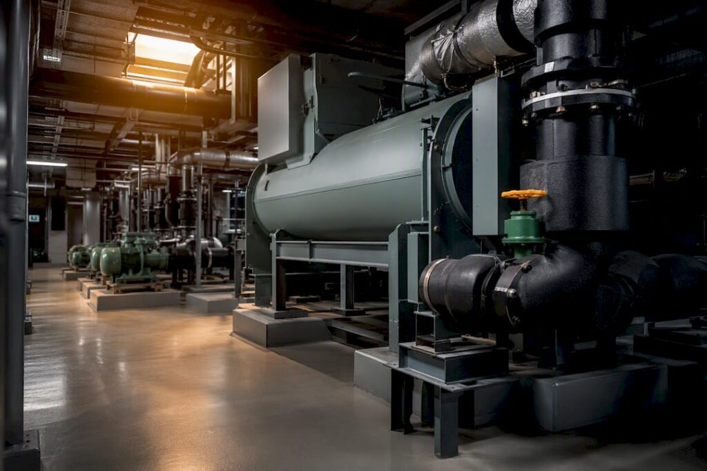
Design chilled-water plants for diversified peak load using hourly load profiles, not a simple sum of nameplate capacities. Specify multiple staged chillers sized between roughly 50% and 100% of that diversified peak, so the plant runs efficiently at partial load and tolerates a unit going offline. Pair that equipment selection with pumps and controls tuned for part-load operation, since most operating hours fall well below design conditions.
TL;DR:
- Using hourly load profiles rather than simple summation allows for more accurate sizing of multiple staged chillers, typically between 50% and 100% of peak load.
- Proper loop relationships, including condenser flow rates and tower capacity, are critical for efficiency, especially during part load, and must be confirmed before equipment selection.
- Redundancy should be based on actual diversified peak load, favoring N+1 for critical applications, with energy estimates from manufacturer data against real load profiles.
- Variable-frequency drives on pumps, staged towers, and condenser flow sequencing can cut plant energy consumption by up to 30%, especially in climates with extended low load periods.
- Effective control sequences that adjust for real-time demand, outdoor conditions, and system performance are essential for maintaining efficiency and avoiding low delta-T syndrome.
Table of Contents
- What Are the Core Components of Chilled Water System Design?
- How Do You Size Chillers and Plan for Redundancy?
- Which Pumping Scheme Fits Your Chilled Water System Layout?
- How Do You Manage Delta-T and Avoid Low Delta-T Syndrome?
- How Do You Select Chillers, Towers, and Pumps for Long-Term Performance?
- What Control Sequences Keep a Chilled Water Plant Efficient?
- Where Do VFDs and Waterside Economizers Pay Off Fastest?
- What Belongs on a Chilled Water System Commissioning Checklist?
- Practitioner Lessons From Singapore Project Experience
- Thermal Storage Integration and Design Considerations
- How Do You Manage Water Treatment and Quality?
- Noise and Vibration Control Strategies
- Safety Considerations and Code Compliance Standards
- Impact of System Design on Indoor Air Quality
- A Practical Take on Chilled Water System Design Today
- How Stellar Structures Supports Your Chilled Water Project
- Sources
- FAQ
What Are the Core Components of Chilled Water System Design?
A chilled water system is built around five interconnected loops, and a design error in any one of them shows up as an inefficiency or a failure somewhere else. The chiller evaporator loop removes heat from the building’s chilled water; the condenser water loop rejects that heat to the cooling tower; the chilled-water distribution loop carries cooled water to air handling units (AHUs) and fan coil units (FCUs); the coil loop at each AHU/FCU transfers heat from room air into the water; and the cooling tower air loop discharges heat to the atmosphere through evaporative cooling.
Chiller selection anchors everything downstream. Scroll chillers typically handle loads under 100 tons, screw chillers fill the mid-range, and centrifugal chillers dominate installations of 250 tons and larger, according to design guidelines commonly cited in university engineering standards. Air-cooled units simplify plant rooms and avoid tower water treatment but carry an efficiency penalty in hot, humid climates; water-cooled chillers cost more upfront but deliver materially better part-load performance.
The interdependencies matter as much as any single component choice:
- Condenser water flow rate dictates tower cell sizing and pipe diameter through the entire condenser loop.
- Tower capacity, not just chiller capacity, sets the ceiling on how far you can turn down condenser flow at part load.
- Distribution piping layout (direct return versus reverse return) affects balancing effort and commissioning time.
- AHU/FCU coil selection determines the delta-T the whole plant can realistically achieve.
Get the loop relationships right on paper before selecting a single piece of equipment, and the rest of the design process moves faster with fewer surprises during commissioning.
How Do You Size Chillers and Plan for Redundancy?
Peak diversified load (PDL) is the maximum simultaneous cooling demand the building actually produces, accounting for the fact that not every zone peaks at the same hour. It is almost always lower than the sum of individual room or zone peak loads, and sizing a plant to the undiversified total wastes capital and locks chillers into inefficient part-load operation for most of their service life.
The preferred workflow has two tiers. Where an existing building or a similar reference facility has building automation system (BAS) trend data, use it directly; measured performance beats any model. For new construction, run an ASHRAE 90.1 Appendix G–compliant hourly simulation rather than relying on peak-day load alone. Combining that hourly profile with proven rules of thumb produces better staging and equipment selection than either approach used in isolation.
Statistic Callout: Design guidelines generally call for multiple chillers once a plant exceeds roughly 400 tons of diversified load, with each unit sized between about 50% and 100% of PDL so that staging one, two, or three units still tracks the load curve efficiently.
Work through sizing and redundancy in this order:
- Establish PDL from BAS data or compliant simulation, not from adding up room-by-room peaks.
- Select chiller type and count using the capacity bands above, favoring at least two identical units for any plant serving critical loads.
- Set a baseline chilled-water delta-T target, commonly around 7 to 8°C (14°F), as the starting point for pipe and pump sizing.
- Confirm minimum flow requirements for each chiller model to avoid nuisance trips at low load.
- Decide between N and N+1 redundancy based on the consequences of a cooling outage: a data center or hospital justifies N+1 on life-cycle grounds even where the added capital cost looks steep on paper.
- Require every chiller manufacturer to submit annual energy estimates calculated against your project’s actual load profile, not against a generic rating condition, before you sign off on procurement.
That last step separates a defensible selection from a guess. Two chillers with identical full-load efficiency numbers can differ by a wide margin in real annual energy use once you weight their performance across the hours the building actually spends at 30% or 50% load.
Which Pumping Scheme Fits Your Chilled Water System Layout?
Primary-only, primary-secondary, and variable-primary configurations each solve the flow-matching problem between chillers and the distribution loop differently, and the choice affects commissioning time as much as it affects energy use.
Primary-secondary systems decouple constant chiller flow from variable distribution flow using a common pipe or low-loss header, which simplifies chiller protection but adds a second set of pumps and control points. Primary-only variable flow eliminates the secondary pump set entirely, cutting first cost and pumping energy, but it demands tighter control coordination because chiller flow must track building demand directly without a buffer. Variable-primary designs, now common in new builds, push variable-speed drives (VFDs) onto the primary pumps themselves and rely on a bypass valve to protect minimum chiller flow during low-load hours.
Constant-flow distribution was standard in older buildings, but variable-flow distribution dominates current chilled water system design because pump power follows the cube of speed. A modest reduction in pump speed at part load yields an outsized energy saving, which is why VFDs on secondary and primary pumps rank among the highest-return investments in the entire plant.
Practical pump arrangement guidance worth following on every project:
- Pipe pumps directly to individual chillers rather than through a headered arrangement that depends on automatic flow-balance valves, which have a documented history of reliability problems in larger plants.
- Provide a single redundant pump valved into service rather than duplicating pumps one-for-one on every chiller.
- Size the minimum-flow bypass control loop to protect chiller evaporators without recirculating so much flow that it masks true building demand from the BAS.
Pro Tip: In high-rise applications, run a hydraulic model that checks pump head against the full vertical lift plus friction loss at both minimum and maximum flow. A pump selected only for design-day flow often cavitates or hunts at the low-load conditions the building spends most of its life in.
How Do You Manage Delta-T and Avoid Low Delta-T Syndrome?
Delta-T, the temperature difference between supply and return chilled water, drives pump sizing, pipe sizing, and chiller capacity all at once. A plant designed around a 14°F (7 to 8°C) delta-T moves half the flow of one designed around a 7°F delta-T for the same cooling output, which cuts pump horsepower roughly in proportion and shrinks pipe diameters throughout the distribution loop.
Low delta-T syndrome, where actual return water temperature runs closer to supply than design intended, is one of the most common and costly problems in operating chilled water plants. It forces pumps to run faster and chillers to work harder to deliver the same cooling, eroding the efficiency gains the design assumed on paper. The root cause is usually terminal-side control behavior, particularly three-way valves that bypass water instead of throttling it, or coil valves with poor authority at low flow, according to guidance drawn from the same design guideline series referenced above.
Pipe and valve sizing choices that protect delta-T over the life of the system:
- Size distribution piping for a velocity that balances head loss against pipe cost, typically keeping trunk mains under about 10 feet per second.
- Specify two-way modulating control valves at coils rather than three-way bypass valves wherever the control sequence allows it.
- Insulate chilled-water piping to a thickness that limits heat gain to a small fraction of coil load, particularly on exposed rooftop or mechanical-room runs.
When low delta-T shows up after occupancy, the fix is rarely more chiller capacity. Retune pump curves and control loops first, review terminal valve authority, and consider a supply-temperature reset strategy before assuming the plant is undersized.
How Do You Select Chillers, Towers, and Pumps for Long-Term Performance?
Match chiller type to capacity band first, then evaluate part-load performance metrics, specifically coefficient of performance (COP) and integrated part-load value (IPLV), rather than full-load efficiency alone. Require vendors to submit annual energy projections calculated against your specific hourly load profile rather than a generic rating point.
Cooling tower selection deserves the same scrutiny as chiller selection. Sizing tower cells with more surface area than the chiller’s rated condenser flow strictly requires gives the plant turndown headroom, letting fans and condenser pumps slow down at part load without losing heat rejection capacity.
Statistic Callout: Applying variable-speed drives, staged tower operation, and variable condenser flow together, with proper sequencing, can cut plant energy consumption by an estimated 15% to 30% compared to constant-speed, single-stage operation.
Equipment notes worth building into your specification:
- Choose split-coupled pumps over close-coupled or vertical-inline units where seal replacement without disturbing piping alignment matters for maintainability.
- Specify VFDs on both primary/secondary chilled-water pumps and condenser water pumps, not just one loop.
- Reducing condenser and chilled-water flow rates below older rule-of-thumb defaults can lower first cost and energy draw across the plant, provided pipe and pump selections are rechecked against the new flow targets, per Trane’s application guidance.
What Control Sequences Keep a Chilled Water Plant Efficient?
A control sequence built for design-day conditions and left unchanged for part-load hours is a common reason a plant underperforms in operation. Sequencing should actively track the varying load curve rather than just reacting to peak conditions.
Build the sequence around these strategies, roughly in order of impact:
- Demand-based chiller staging that brings additional chillers online only when combined load and minimum-flow constraints require it, avoiding the common mistake of staging by a fixed load percentage alone.
- Trim-and-respond logic for differential pressure setpoints, letting the control loop find the lowest pressure setpoint that still satisfies the most demanding zone rather than holding a fixed design-day setpoint.
- Chilled-water supply temperature reset tied to outdoor air conditions or building load, raising supply temperature during low-load hours to improve chiller efficiency.
- Cooling tower setpoint optimization that balances condenser water temperature against fan energy rather than chasing a single fixed setpoint year-round.
Commissioning and ongoing operations should track a specific set of sensors: chilled and condenser water supply/return temperatures, flow at each chiller, pump speed and power, and tower fan status. Trend that data over representative hot, mild, and shoulder-season days, not just the design day, to confirm the sequence performs as intended.
Write procurement specifications that require manufacturers to state annual energy performance against your load profile. A chiller quoted only on full-load kW per ton tells you almost nothing about how it will behave across the thousands of part-load hours it will actually see.
Where Do VFDs and Waterside Economizers Pay Off Fastest?
Pump power scales with the cube of speed, so a pump running at 80% speed draws roughly half the power of one running at full speed. That relationship is why VFDs on secondary chilled-water pumps consistently rank as the fastest-payback upgrade in a chilled water system, ahead of chiller replacement or tower upgrades in most retrofit scenarios.
Statistic Callout: Combined VFD, tower-staging, and variable condenser-flow strategies can deliver 15% to 30% energy reductions relative to constant-speed baseline operation, a figure covered earlier that applies directly to retrofit payback calculations.
Waterside economizers, which use the cooling tower to produce chilled water directly during favorable outdoor conditions, pay off fastest in climates with extended periods of low wet-bulb temperature. In consistently hot, humid climates the economic case weakens considerably, and the capital may return more value invested in VFDs and tower staging instead.
To decide where to spend, run a life-cycle cost comparison, not a first-cost comparison:
- Estimate annual operating hours at each load band from the hourly profile, then apply expected power draw at each band.
- Compare simple payback for VFD retrofits, tower-cell additions, and economizer piping against their respective installed costs.
- Weight decisions toward measures with paybacks under five years unless the project has a specific sustainability mandate justifying longer horizons.
What Belongs on a Chilled Water System Commissioning Checklist?
Commissioning verifies that the plant as built performs the way the design intended, and skipping steps here is how low delta-T syndrome and short-cycling problems slip into daily operation undetected.
Follow this sequence:
- Review the sequence of operation document against the actual installed controls points list before any functional testing begins.
- Perform point-to-point checkout on every sensor, actuator, and control point to confirm wiring and calibration match the design.
- Run functional performance tests across the full range of operating modes, including chiller staging, standby pump failover, and economizer switchover where applicable.
- Trend key data (delta-T, flow, pump speed, chiller kW/ton) over multiple representative days, not a single test day, and compare against design tolerances.
Maintenance items that preserve the energy performance the design achieved include regular coil and tower cleaning, an active water treatment program, and periodic pump alignment and seal checks; a maintenance program that skips these steadily erodes delta-T and heat transfer over a few operating seasons.
Practitioner Lessons From Singapore Project Experience
Chilled water plants designed for Singapore’s climate face year-round high wet-bulb conditions, which shrinks the practical case for waterside economizers and puts more design weight on chiller and pump part-load efficiency instead. Coastal and reclaimed-land sites add another layer: condenser water piping, plant-room equipment, and support structures all face accelerated corrosion risk that ordinary specifications underestimate, a challenge covered in detail in Stellar Structures’ work on structural design near the sea.
Industrial projects with high, steady thermal loads, cold storage and process cooling facilities among them, demand a different sizing logic than office towers, since the load curve is flatter and redundancy decisions carry a higher operational cost when they fail. Stellar Structures’ engineering teams draw on this range of project types, from high-rise commercial towers to industrial facilities with high thermal loads, when advising on M&E systems that must satisfy both performance targets and authority submission requirements.
Thermal Storage Integration and Design Considerations
Thermal energy storage, typically chilled-water or ice-based tanks, lets a plant shift chiller operation away from peak electricity demand periods and toward off-peak hours, sometimes reducing installed chiller capacity itself since the tank absorbs a portion of the peak load.
Integrating storage into a chilled water system design changes several downstream decisions. The primary loop must be configured to charge the tank during low-load hours (often overnight) and discharge it during the afternoon peak, which typically requires a dedicated set of storage pumps and a diverting valve arrangement separate from the main distribution loop. Chiller sizing calculations shift too: instead of sizing purely to PDL, the design team sizes to a lower “charging” capacity plus the storage volume needed to cover the peak shortfall, which demands an accurate hourly load profile rather than a single peak-day number.
Tank sizing depends heavily on the temperature differential achievable between charge and discharge cycles; a wider delta-T reduces tank volume for the same stored capacity, which is one more reason delta-T management deserves attention early in design rather than as an afterthought. Stratified chilled-water tanks need careful diffuser design to prevent mixing between warm and cold layers, since a poorly designed diffuser can destroy hours of stored capacity in a single charge cycle.
Storage makes the most economic sense on projects facing time-of-use electricity tariffs or utility demand charges, and on plants where reducing installed chiller tonnage offsets a meaningful share of the tank’s capital cost. It rarely pays for itself on smaller commercial buildings with flat load profiles and no demand-charge exposure.
How Do You Manage Water Treatment and Quality?
Water quality in both the condenser water and chilled-water loops directly affects heat transfer efficiency, equipment life, and delta-T stability, yet it is one of the most frequently under-specified parts of a chilled water system.
Condenser water loops, being open to atmosphere through the cooling tower, are the most exposed to scaling, corrosion, and biological growth. A treatment program combining chemical dosing (biocides, scale inhibitors, corrosion inhibitors) with regular blowdown to control dissolved solids concentration is standard practice, and the specification should state target ranges for conductivity, pH, and biocide residual rather than leaving treatment entirely to an operations contractor after handover.

Chilled-water loops, being closed systems, face a different set of risks: corrosion from dissolved oxygen introduced during fill and top-up, and fouling from particulates left over from construction. A closed-loop treatment program typically includes an initial chemical clean and flush before commissioning, followed by periodic testing for pH, corrosion inhibitor concentration, and iron content.
Fouled heat transfer surfaces, whether from scale in the condenser or sediment in chiller tubes, reduce the plant’s ability to hit design delta-T and push chillers toward higher energy use for the same cooling output. Specifying water treatment scope, testing frequency, and acceptance criteria as part of the design package, rather than deferring it to a separate facilities contract, keeps this risk from becoming an operational surprise in year two.
Noise and Vibration Control Strategies
Chillers, pumps, and cooling towers all generate mechanical noise and vibration that can travel through piping, structural connections, and building slabs if isolation is not designed in from the start.
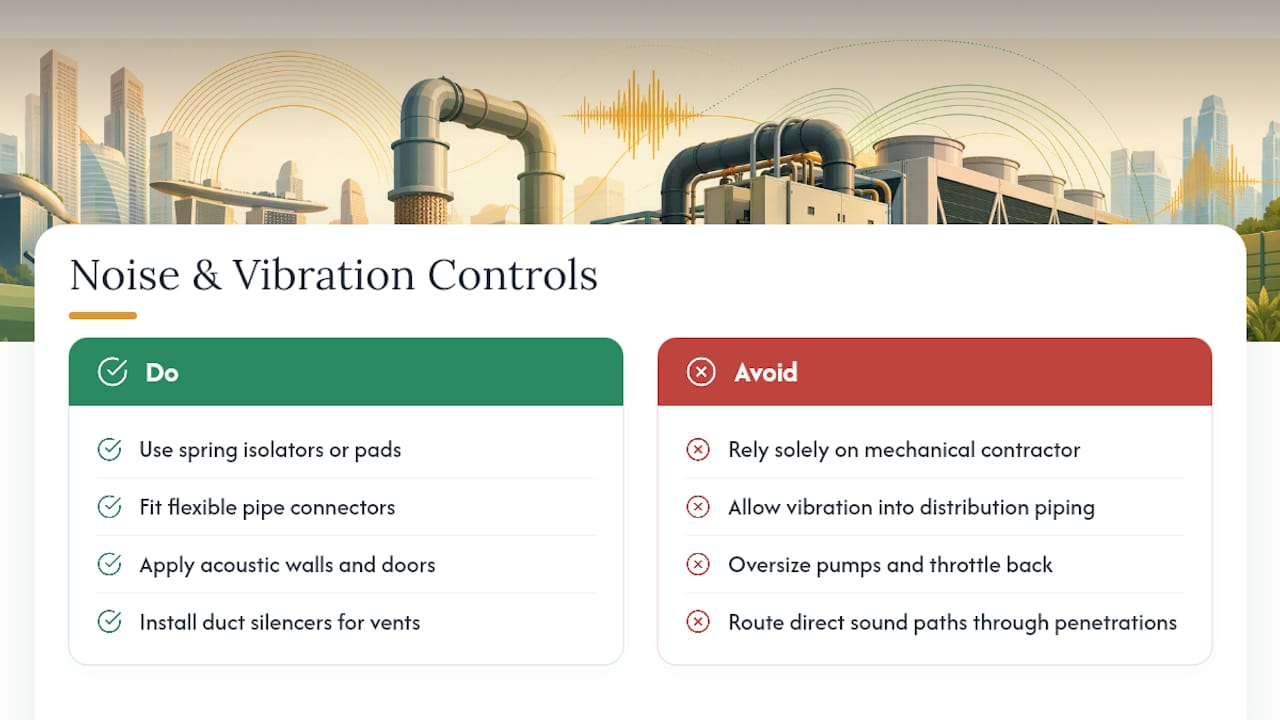
Vibration isolation typically starts at the equipment mounts. Spring isolators or isolation pads under chillers and pumps decouple rotating equipment from the structural slab, and the isolator selection depends on the equipment’s operating frequency relative to the structure’s natural frequency, a calculation best coordinated with the structural engineer rather than left to the mechanical contractor alone. Flexible pipe connectors at chiller and pump connections prevent vibration from transmitting into the distribution piping network, where it can travel long distances and re-radiate as noise in occupied spaces far from the mechanical room.
Noise control in plant rooms adjacent to occupied space usually requires a combination of acoustic wall and door treatments, duct silencers on any ventilation serving the mechanical room, and careful routing of piping penetrations to avoid direct sound paths. Cooling towers deserve particular attention on high-rise projects, since fan and water-splash noise at the roof level can affect upper floors of the same building or neighboring structures, and low-noise fan selections or acoustic tower enclosures are often necessary to meet site noise limits.
Pump selection also plays a role here: split-coupled pumps generally run quieter than close-coupled units at the same duty point, and correctly sized pumps operating near their best efficiency point produce less vibration than oversized pumps throttled back with a control valve. Coordinating mechanical equipment layout with the structural design early avoids costly retrofits of isolation systems after occupants report noise complaints.
Safety Considerations and Code Compliance Standards
Chilled water system design intersects several regulatory domains at once: pressure vessel safety, refrigerant handling, electrical safety for pumps and controls, and structural loading for suspended and floor-mounted equipment.
Refrigerant selection and containment carry specific code implications depending on the refrigerant class used in the chiller, and machine room ventilation, refrigerant detection, and emergency egress requirements typically follow from that selection.
Electrical safety extends beyond simple code compliance for pump and chiller circuits; VFDs introduce harmonics and require coordination with the electrical engineer on wiring practices and grounding to avoid nuisance trips and equipment damage. Structural support for chillers, pumps, and rooftop cooling towers needs to account for both static weight and dynamic loading from vibration and, on rooftop installations, wind loading, which is why mechanical and structural design checks should run in parallel rather than sequentially. Authority submissions in Singapore typically require sign-off from multiple bodies depending on project scope, and coordinating M&E design against structural design checks early avoids late-stage conflicts that delay approval.
Impact of System Design on Indoor Air Quality
Chilled water system design shapes indoor air quality far more directly than most building occupants realize, largely through its effect on humidity control and coil condensation management at the AHU and FCU level.
Chilled-water supply temperature and coil selection together determine how much moisture the system removes from supply air. A system designed with too high a supply temperature, often in an effort to save chiller energy, can struggle to maintain adequate dehumidification, raising indoor relative humidity into a range that supports mold and dust mite growth. Conversely, coils that run consistently wet without adequate condensate drainage and drain pan cleaning become a biological growth site of their own, one that recirculates spores and odors back into occupied space through the supply air stream.
Delta-T management connects here too: a plant suffering from low delta-T syndrome often responds by lowering supply temperature to compensate, which increases the risk of coil icing and drain pan overflow, and in some cases prompts operators to bypass dehumidification controls entirely just to keep the space cool. Getting the hydraulic design and control sequencing right, as covered earlier, is not purely an energy question. It is also what keeps coils properly wet (not soaked), drainage adequate, and humidity in the range that supports occupant health rather than undermining it.
A Practical Take on Chilled Water System Design Today
The industry’s rules of thumb for chiller sizing bands and PDL still hold up, and engineers who skip them in favor of pure simulation often end up with plants that are numerically optimized but operationally fragile. The real gap is not between rules of thumb and modeling. It is between either approach used alone and the two used together, checking simulation output against sizing bands and flagging designs that drift too far from either.
Where conventional guidance falls short is part-load control sequencing. That gap is where delta-T degrades, pumps run inefficiently, and energy savings promised on paper never materialize in utility bills.
If there’s one priority to fix first, it is building the hourly load profile before selecting a single piece of equipment, and writing procurement specifications that hold vendors accountable to that profile rather than to a single rating-point number. Everything downstream, from redundancy strategy to control sequencing, gets easier to defend in an authority submission once that foundation is in place.
— Aman
How Stellar Structures Supports Your Chilled Water Project
Getting a chilled water system from load calculation to a signed authority submission requires coordinated M&E design, structural coordination for plant rooms and equipment support, and a clean path through approvals from bodies like BCA and SCDF. A full engagement approach pairs mechanical design with the civil, structural, and geotechnical checks that plant rooms, chiller yards, and rooftop cooling towers actually depend on.

A typical engagement starts with a design review of your load profile and equipment schedule, moves through coordinated M&E and structural design checks, and ends with the documentation package needed for submission. Deliverables usually include sized equipment schedules, coordinated plant-room layouts, and the structural calculations that support them, a scope covered in more depth on Stellar Structures’ civil and structural design checks service page. If your project needs that kind of coordinated design and authority submission support, get in touch to scope the engagement against your current design stage.
Sources
For deeper design checks, consult the University of Michigan design guideline for sizing rules, CoolTools for load-profile methodology, and Trane’s design catalog for flow-reduction procurement templates.
- DESIGN GUIDELINE 230050 CHILLED WATER SYSTEMS
- CoolTools Chilled Water Plant Design and Performance Specification Guide
FAQ
What Are the Different Types of Chilled Water Systems?
Chilled water systems are typically classified by pumping scheme (primary-only, primary-secondary, or variable-primary) and by chiller cooling method (air-cooled or water-cooled), with the choice depending on plant size, redundancy needs, and available space for cooling towers.
What Are the Main Components of a Chilled Water System?
The main components are chillers, cooling towers or air-cooled condensers, primary and secondary pumps, distribution piping, and the air handling units or fan coil units that deliver cooling to occupied space.
What Is a Type 3 Chiller?
Chiller classifications vary by manufacturer and code jurisdiction rather than following one universal numbering scheme, so “type 3” typically refers to a specific compressor or refrigerant classification used in a particular equipment catalog or local code rather than a standardized industry-wide category.
What Are the Disadvantages of a Chilled Water System?
Chilled water systems carry higher upfront capital cost and mechanical complexity than direct-expansion systems, require dedicated plant-room space and ongoing water treatment, and demand more sophisticated commissioning and controls expertise to avoid problems like low delta-T syndrome.
Recommended
- QP Design vs QP Supervision: Why One Engineer Might Not Be Enough
- Why Multi Disciplinary Experience Matters in a QP S Design Approach
- Checklist for Developers Contractors Choosing the Right QP S and Supervision Team for Your Next Build in Singapore
- Understanding what is the cost of hiring a qp s: A Comprehensive Guide