




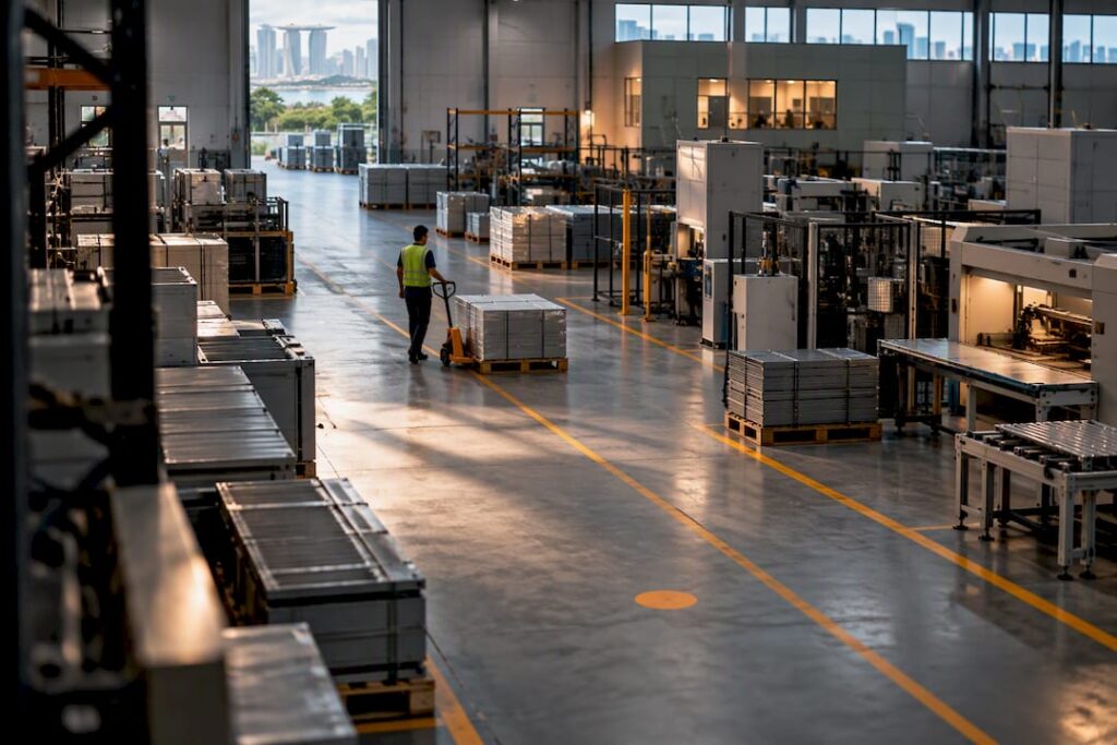
Industrial facility layout is the physical arrangement of equipment, storage, workstations, walkways, and personnel that supports a production process. The single priority a layout design must get right is the balance between material flow efficiency and life-safety compliance, since throughput gains mean little if fire compartmentation or egress requirements later force a costly redesign. This guide covers layout types, planning methodology, flow metrics, simulation tools, regulatory constraints, phased implementation, and where Stellar Structures fits into that process.
TL;DR:
- Layout decisions should prioritize balancing material flow efficiency with compliance to fire safety, egress, and structural regulations from the start.
- Using structured methods like Systematic Layout Planning combined with lean tools and ergonomics significantly reduces material movement distances and improves space utilization.
- Digital twin simulation and multi-objective optimization can identify potential bottlenecks, congestion, and worker fatigue before construction begins.
- Regulatory standards for fire prevention and structural safety directly influence feasible layout configurations, requiring early integration into the design process.
- A phased implementation approach, supported by engineering and authority coordination, minimizes operational disruption during layout changes.
Table of Contents
- Facility layout types and how to choose between them
- How to plan a layout: SLP, lean methods, and ergonomics
- Measuring material flow: the metrics that prove a layout works
- Choosing the right modeling tools for each design stage
- Regulatory limits that shape what a layout can become
- Rolling out a new layout without stopping production
- Engineering support behind a compliant industrial layout
- What actually separates good layouts from good-looking ones
- Where Stellar Structures fits into your layout project
- Where to verify these standards and figures
- Sources
- FAQ
Facility layout types and how to choose between them
Facility layout, plant layout, and warehouse layout describe overlapping ideas at different scales. Facility layout is the broadest term, covering the arrangement of an entire site. Plant layout usually refers to production floor arrangement within a manufacturing building, while warehouse layout focuses specifically on storage, picking, and dispatch zones. Most industrial projects require decisions across all three simultaneously.
Five layout families cover nearly every industrial scenario:
- Process (functional) layout groups similar machines or skills together, such as all welding stations in one bay; it suits low-volume, high-variety production but generates longer travel distances between departments.
- Product (line) layout arranges equipment in the sequence a product follows, minimizing handling for high-volume, standardized output but offering little flexibility when product mix changes.
- Cellular layout clusters machines into self-contained cells that produce a family of similar parts, blending the flexibility of process layouts with much of the flow efficiency of product layouts.
- Fixed-position layout keeps the product stationary while labor, tools, and materials move to it, common in shipbuilding, aircraft assembly, and large structural fabrication.
- Combination (hybrid) layout blends two or more of the above, often a cellular core feeding a product line, which reflects how most real factories actually operate.
Choosing between them depends on production volume, product variety, and how often the process changes. A facility running a single high-volume product benefits from a line layout, while a contract manufacturer serving varied orders typically needs a process or cellular arrangement. Hybrid layouts are appropriate whenever a single family covers only part of the operation, which describes most mid-size industrial sites.
How to plan a layout: SLP, lean methods, and ergonomics
Systematic Layout Planning (SLP) remains the backbone of practical layout design because it turns qualitative relationships into a structured, comparable format. The method starts by listing every functional area, then scoring the closeness required between each pair on a relationship chart (absolutely necessary, especially important, important, ordinary, unimportant, undesirable). That chart becomes an adjacency matrix, which then drives space-relationship diagrams and, eventually, block layouts that respect both flow priorities and available floor area.
Value Stream Mapping (VSM) and 5S sharpen the inputs SLP relies on. VSM exposes where material and information actually move, separating value-adding steps from waiting, rework, and excess transport, which often reveals that departments assumed to be close in the current layout are actually separated by several handoffs. 5S then disciplines the physical zones themselves, sorting, organizing, and standardizing workstations so that the space allocated in the new layout matches real operating needs rather than accumulated clutter.
Ergonomics belongs inside this same planning pass, not as an afterthought. Reach envelopes, walk-time targets between a workstation and its material source, and sightlines for supervision all shape where equipment and storage can practically sit. A workstation that meets throughput targets but forces repeated overreach or long walks will underperform once fatigue sets in.
A workable process map follows four stages:
- Define functional and space requirements for every department, cell, or line.
- Build the adjacency matrix and relationship chart from SLP.
- Generate two or three candidate block layouts that satisfy the highest-priority adjacencies.
- Validate each candidate against flow metrics and safety constraints before committing to detailed design.
Pro Tip: Score adjacency relationships with your operations team present, not from an org chart alone, since the people running the floor usually know which departments actually depend on each other.
Measuring material flow: the metrics that prove a layout works
A layout proposal is only as credible as the metrics behind it. The core KPI set for any industrial layout includes throughput (units completed per period), travel distance (total distance material or people move per cycle), space utilization (productive area divided by total floor area), work-in-process (WIP) inventory, and bottleneck stress at the busiest station or aisle.
Collecting reliable data for these metrics matters as much as the metrics themselves:
- Time studies capture cycle times and handling delays at individual workstations.
- RFID or IoT tracking records the actual path materials take across the floor, rather than the path assumed on paper.
- Production logs provide throughput and downtime history to validate simulation baselines.
Traditional From-To charts, which tally movement between department pairs, tend to understate real travel because they miss multistep sequences where a part visits four or five areas before completion. Capturing full travel sequences, ideally through tracking rather than manual logging, gives a more honest baseline before any redesign work begins.
Spaghetti diagrams remain a simple, visual way to expose crossing paths and backtracking, while flow matrices and simulation outputs quantify how much a proposed layout actually improves on the baseline. The evidence for combining these techniques is substantial: a 2024 study on a steel-processing facility found that pairing SLP with lean techniques such as VSM and 5S cut material flow distance by 34% and improved space utilization by 26%.

A 2024 SLP-plus-lean study cut material flow distance by 34% and lifted space utilization by 26%, which shows how much a structured methodology recovers before any capital investment in new equipment. Separate simulation research applying reinforcement learning to factory layout optimization reported a 0.3% throughput gain alongside a 3.8% reduction in logistics movement distance and an 11% cut in required AGVs, evidence that even marginal layout refinements can lower fleet and infrastructure costs.
Choosing the right modeling tools for each design stage
Layout tools follow a natural progression as a project matures. Early concept work still belongs on 2D sketches, since they are fast to iterate and cheap to discard. Once a candidate layout survives that first filter, moving into 3D CAD or building information modeling (BIM) lets engineers check clearances, sightlines, and structural interfaces that a flat drawing cannot reveal. The final validation stage, before any physical change, should run through a digital twin paired with simulation. Autodesk’s plant layout guidance recommends exactly this integrated 2D and 3D digital-twin workflow to simulate and validate layout decisions before committing to implementation.
Simulation type should match the question being asked:
- Discrete-event simulation suits queue-driven systems, such as a line with variable batch sizes moving through shared machines.
- Agent-based simulation captures individual worker or vehicle behavior where interactions between agents matter more than a fixed sequence.
- Multi-agent robotic simulation is warranted once automated guided vehicles (AGVs) or mobile robots share the floor with people, since collision risk and path contention need explicit modeling.
Optimization methods add a further layer once the basic layout is established. Multi-objective optimization frameworks generate Pareto-optimal solution sets that let planners trade off throughput, space utilization, and worker well-being rather than chase a single metric in isolation, an approach detailed in recent decision-support research on factory layout. Generative-AI approaches to layout generation are emerging but remain worth their added complexity mainly on large, frequently reconfigured facilities, not on a single-line retrofit.
Pro Tip: Match model fidelity to the decision at hand: a coarse block-layout simulation is enough to choose between candidates, but commissioning a specific automation cell justifies a higher-fidelity, longer run-time model.
Regulatory limits that shape what a layout can become
Fire safety and structural regulations are not a compliance step to handle after the layout is finished; they define which layouts are physically buildable in the first place. The Code of Practice for Fire Precautions in Buildings (Fire Code) sets compartmentation sizes, purpose-group classifications, and mezzanine-specific rules that directly constrain how departments, storage blocks, and elevated work platforms can be arranged.
These constraints reshape layout decisions in predictable ways:
- High-bay warehouses often need additional compartmentation or sprinkler protection once storage height crosses defined thresholds, which limits how racking can be consolidated.
- Chemical or hazardous processing areas typically require dedicated fire compartments and separation distances that force certain departments apart, regardless of flow efficiency.
- Mezzanine additions carry area and occupancy limits that determine whether a mezzanine can house production, storage, or must remain a lighter-duty platform, a topic covered in more detail in our industrial platform design approval guidance.
Before finalizing any layout, assemble a Fire Safety Report, a process flow diagram showing hazardous material movement, and evidence of early coordination with the relevant authority. Building these safety limits into the digital model from the start, rather than retrofitting them after a layout is chosen, avoids the redesign cycles that consume the most schedule time. Our guide to fire risk assessment for industrial facilities walks through that integration in more detail.
Rolling out a new layout without stopping production
A phased rollout protects output while a layout changes underneath it. Six stages cover most industrial projects:
- Concept layout, built from SLP adjacency work and early flow targets.
- Simulation validation, confirming the concept meets throughput and safety criteria before detailed design begins.
- Detailed design, translating the validated concept into structural, M&E, and equipment-specific drawings.
- Authority submissions, covering fire safety, structural, and any mezzanine or platform approvals required for the specific project.
- Staged implementation, moving equipment in defined blocks rather than all at once.
- Commissioning, verifying that installed equipment and flow paths match the validated design.
Operational protection tactics matter as much as the phase sequence itself:
- Run new cells as a pilot alongside the existing line before a full cutover.
- Schedule heavy equipment moves during night shifts or planned downtime windows.
- Switch departments over in stages rather than shutting the whole floor at once.
A clear stakeholder map keeps the phasing realistic. Operations owns throughput targets, safety teams own compliance sign-off, facilities manages the physical move, and procurement tracks equipment lead times, all of which need visibility into the same schedule. For executive sign-off, ROI estimates should tie directly to the flow metrics gathered earlier: a layout that recovers 34% of travel distance, as seen in documented SLP-plus-lean projects, translates into measurable labor-hour savings that justify the disruption of a staged move.
Engineering support behind a compliant industrial layout
Layout decisions rarely stay separate from structural and authority requirements for long. Professional engineering design and authority submission facilitation can help ensure that layout changes involving new mezzanines, platforms, or structural modifications are assessed and approved efficiently, reducing the need to switch between multiple consultants.
Mezzanine and platform conversions are a common trigger for layout redesign, since adding usable floor area changes adjacency options across an entire facility; our industrial platform design approval work covers the structural and approval considerations specific to that scenario.
Authority coordination is often the slowest part of any layout project. Managing submissions across relevant statutory boards can cover most of the approvals an industrial layout change is likely to trigger, from structural modifications to fire safety compliance and environmental clearances.

What actually separates good layouts from good-looking ones
Digital twins and simulation have become the default validation step for industrial layouts, and that shift is overdue: a layout that only looks efficient on a 2D block diagram can still fail once real travel sequences, congestion, and human fatigue enter the picture. Multi-objective decision support now lets planners see the trade-off between throughput and worker well-being explicitly, rather than discovering it months later through turnover or repetitive strain complaints.
The judgment that still matters most is knowing which constraints are non-negotiable. Fire compartmentation and egress requirements should enter the model on day one, not as a late correction once a layout already has emotional buy-in from operations.
— Aman
Where Stellar Structures fits into your layout project
A well-modeled layout still needs structural sign-off, M&E coordination, and authority approval before it can be built, and that is where a project usually loses months if the engineering and submission work is split across separate firms. Stellar Structures handles both sides under one engagement.
Services most relevant to a layout project include:
- Structural, civil, and geotechnical engineering design and consultation for new equipment foundations, mezzanines, or platform additions.
- Mechanical and electrical (M&E) engineering design to align services with the revised floor plan.
- Authority submissions across BCA, URA, JTC, SCDF, PUB, LTA, NEA, and NParks, so approvals move in parallel with design rather than after it.
For teams ready to scope a layout change that involves structural or authority work, the full range of services outlines what a project engagement covers, and Stellar Structures can quote based on the specific scope once initial requirements are shared.
Where to verify these standards and figures
The SCDF Fire Code remains the primary reference for compartmentation and mezzanine rules cited above. The steel-processing SLP and lean case study and the reinforcement-learning simulation study supply the flow and throughput figures referenced in this guide. Autodesk’s plant layout guidance covers digital-twin and simulation workflow recommendations in further depth.
Sources
- Design of an improved layout for a steel processing facility using SLP and lean manufacturing techniques
- Production-simulation-based reinforcement learning for factory layout optimization
- Code of Practice for Fire Precautions in Buildings 2023
- Software for designing a manufacturing plant layout | Autodesk
FAQ
What is a facility layout?
A facility layout is the physical arrangement of equipment, workstations, storage areas, walkways, and personnel within a building to support a specific production or operational process. It determines how materials, workers, and information move through the space, which directly affects throughput, space utilization, and safety.
What are the four main types of facility layouts?
The four core types are process (functional) layout, product (line) layout, fixed-position layout, and cellular layout. Process layouts group similar equipment together, product layouts follow the sequence of production, fixed-position layouts keep the product stationary, and cellular layouts organize machines into cells for a family of similar parts.
What are the 7 types of layout?
Definitions vary across sources, but a common extended list adds combination (hybrid) layout and warehouse-specific layouts, such as U-shaped or straight-through flow, to the four core types. Most industrial facilities in practice use a hybrid that blends cellular and product layout principles rather than a single pure type.
What is industrial layout design?
Industrial layout design is the structured process of planning how equipment, storage, and workflow paths are arranged within a manufacturing or warehouse facility to meet throughput, space, and safety goals. It typically follows methods like Systematic Layout Planning (SLP), incorporates lean tools such as Value Stream Mapping, and is validated through simulation or digital-twin modeling before implementation.
How do digital twins improve industrial layout planning?
Digital twins let engineers simulate material flow, worker movement, and equipment interaction before any physical change is made, catching bottlenecks or safety conflicts that a static drawing would miss. Autodesk’s guidance recommends this simulation-based validation step specifically to avoid costly rework after installation.
Recommended
- Seismic and Wind Load Considerations for Industrial Superstructures in Singapore
- Guide to Industrial Change Applications in Singapore
- The Future of Construction in Singapore: Trends and Insights for 2026