




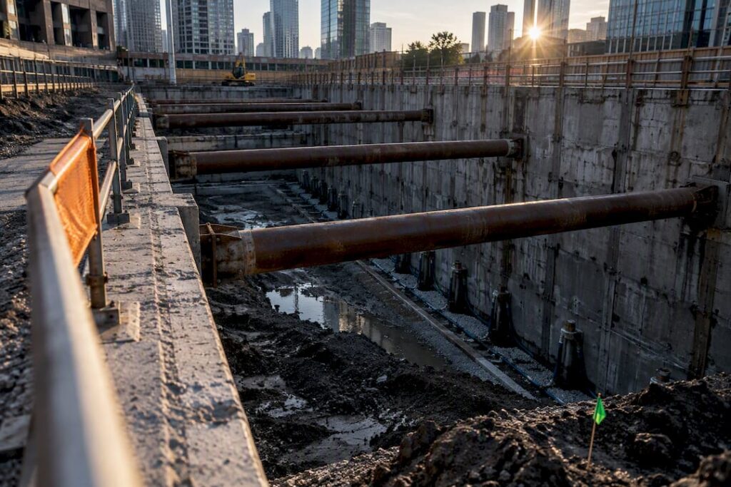
Deep excavation support refers to the temporary or permanent engineered systems, diaphragm walls, secant piles, sheet piles, soldier piles, or internal bracing, that stabilize a vertical or near-vertical cut and prevent soil collapse, groundwater intrusion, and damage to adjacent structures. Engineered support is typically required once a cut exceeds roughly 10 to 14 feet (3 to 4.5 meters), though many jurisdictions mandate design review starting at 5 to 6 feet depending on soil and adjacency conditions. The right system depends primarily on soil type, groundwater behavior, and how close the excavation sits to existing structures.
TL;DR:
- Permanent or temporary support systems are generally required for excavations deeper than 1.5 to 4.5 meters, with stricter regulations for soft soils and high water tables.
- Diaphragm and secant pile walls are preferred for water-tightness in deep or water-sensitive excavations exceeding 15 to 20 meters, while soil nails and soldier piles are suitable for drier, less demanding conditions.
- Proper excavation support design depends on detailed geotechnical data, calibrated numerical modeling, and monitoring plans, with early integration of authority approvals to avoid delays.
- Groundwater control methods vary by soil permeability, including wellpoints, deep wells, or sump pumps, with monitoring of wall movement, groundwater levels, and ground settlement during construction.
- Close coordination with licensed geotechnical engineers and early planning of easements are critical to prevent project failures related to model inaccuracies, groundwater interactions, and approval delays.
Table of Contents
- What Counts as Deep Excavation Support?
- Support System Types: How Each One Works
- How Do You Choose the Right Excavation Shoring System?
- What Goes Into Excavation Support Design?
- Construction Sequencing, Dewatering, and Monitoring
- Author and Stellar Structures: Field Notes From Local Practice
- Where Excavation Projects Go Wrong
- Getting Your Excavation Support Right the First Time
- Sources
- FAQ
What Counts as Deep Excavation Support?
The term covers any structural system built to hold back soil and water while a pit stays open for construction, and, in many cases, after the building is complete. Two features separate deep excavation from a routine trench cut: the depth at which unsupported soil begins to fail, and the presence of groundwater that can destabilize the base or flood the works.
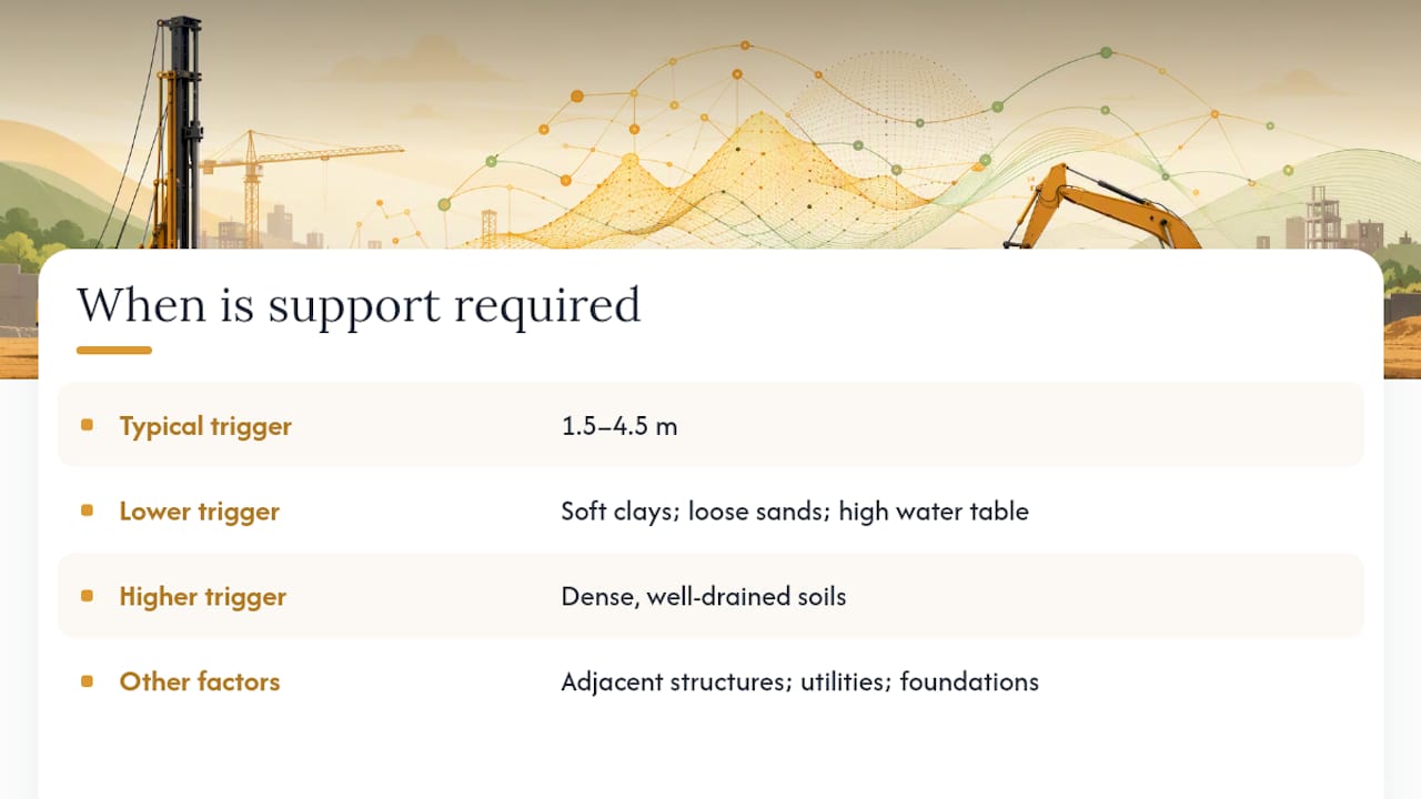
Depth thresholds vary by code and geology, but the general rule of thumb holds across most standards: cuts beyond about 1.5 to 4.5 meters (5 to 14 feet) call for engineered excavation support systems rather than sloped or unsupported sides. Soft clays, loose sands, and high water tables push that trigger depth lower. Dense, well-drained soils can sometimes push it higher, but no responsible engineer treats depth alone as the deciding factor. Adjacent structures, buried utilities, and the sensitivity of nearby foundations often matter more than the number on the drawing.
Support System Types: How Each One Works
Every excavation support system does one of two things: it either closes the boundary against water (a “closed” system) or it leaves the boundary permeable and relies on dewatering (an “open” system). That distinction drives most of the selection logic engineers use on urban sites.
- Diaphragm (slurry) walls: Cast-in-place concrete panels built in a bentonite-filled trench, producing a continuous, watertight wall suitable for deep, permanent, or vibration-sensitive projects. They cost more than driven systems but can double as part of the permanent basement structure, which changes the economics on many projects.
- Secant pile walls: Overlapping bored piles that create a watertight barrier where a diaphragm wall is too expensive or the site is too tight for slurry trench equipment.
- Sheet piles: Interlocking steel sections driven or vibrated into the ground, fast to install and reusable, but driving generates vibration and the interlocks can leak, so they suit sites where groundwater control matters less.
- Soldier pile and lagging: Steel H-piles with timber or concrete lagging between them, economical in firm, dry soils but not watertight, an open system unsuited to high water tables.
- Soil nails and soil-mixing walls (SMW): Lower-cost reinforcement methods that work well above the water table but lose effectiveness, or require heavy dewatering, once groundwater or property encroachment limits apply.
- Tiebacks and internal bracing: Tiebacks anchor into soil beyond the excavation, leaving the pit clear for equipment, but they need a subsurface easement under neighboring land. Struts and rakers avoid that easement problem by bracing internally, at the cost of obstructing the excavation.
- Top-down construction: Uses the permanent floor slabs as horizontal bracing while excavation proceeds beneath already-cast levels, common on dense urban sites where surface disruption must stay minimal.
How Do You Choose the Right Excavation Shoring System?
Selecting among these excavation shoring techniques comes down to five variables that interact rather than stack neatly: depth, groundwater and soil permeability, sensitivity of adjacent structures, easement availability for tiebacks, and vibration limits imposed by nearby occupants or heritage buildings. Cost and schedule matter too, but they follow from the technical constraints rather than driving them.
A few decision rules hold up across most urban projects:
- When groundwater cutoff is required and the excavation exceeds roughly 15 to 20 meters, diaphragm or secant pile walls generally outperform open systems, because the watertight continuity is difficult to replicate any other way.
- When vibration limits are strict, near hospitals, heritage structures, or vibration-sensitive equipment, driven sheet piles are usually ruled out in favor of bored systems.
- When internal space is limited and no easement exists for tiebacks, internal bracing paired with staged excavation, or a top-down sequence, becomes the practical fallback.
- When the retaining wall can be incorporated into the permanent basement structure, a diaphragm wall’s higher upfront cost often gets absorbed into the permanent works budget rather than treated as pure temporary expense.
Regulatory and legal constraints deserve early attention. Tiebacks that cross a property line require a subsurface easement from the neighboring owner, and negotiating that easement can take longer than the design itself. Field comparisons consistently show soil nails as the cheapest, fastest option above the water table, with diaphragm walls as the preferred choice once depth and water sensitivity both increase, and secant piles occupying the middle ground when watertightness matters but a diaphragm wall’s cost or footprint does not fit the site.
Pro Tip: Map your easement requirements before finalizing the support scheme, not after. A tieback system that looks cheapest on paper can lose that advantage entirely if easement negotiations add months to the program.
What Goes Into Excavation Support Design?
Excavation support design starts with the site-specific geotechnical report, never with assumptions carried over from a nearby project. That report should include borehole logs, Standard Penetration Test (SPT) or Cone Penetration Test (CPT) data, groundwater profiling, and, where the aquifer is significant, pumping or slug tests to establish hydraulic conductivity. Skipping this step is the single most common source of underperforming support systems.
From there, engineers typically build a numerical model to predict wall deflection, ground settlement, and strut or anchor loads under staged excavation. Two-dimensional models suffice for long, uniform excavations, but corners, transitions between wall types, and irregular geometry usually need three-dimensional analysis. Software such as PLAXIS and FLAC 3D, paired with constitutive soil models like Hardening-Soil (HS), are standard tools for this work.
- Model calibration against field measurements matters more than model sophistication. A semi-top-down excavation case study in soft clay found that 3D Hardening-Soil analyses matched measured wall deflections within about 5%, but tended to overpredict ground settlement, prompting engineers to apply a correction factor near 0.6 to 0.7 to bring settlement predictions in line with reality.
- Separate simulations using FLAC 3D and elastic support point methods have validated soil-mixing walls and elastic bracing schemes against field data on horizontal displacement across excavation phases.
- Design checks cover lateral earth pressure, basal heave potential in soft clays, wall bending moment capacity, and strut or anchor stiffness under staged loading.
Settlement correction factor: 0.6 to 0.7 applied to raw HS-model outputs in the soft-clay case study cited above, reflecting a consistent pattern of overprediction rather than a universal constant.
Because soil properties vary spatially even within a single borehole grid, probabilistic design is gaining traction over purely deterministic calculations. Treating soil strength and stiffness as distributions rather than fixed values gives engineers a more honest picture of the range of possible wall movement, rather than a single number that field conditions promptly contradict.
Construction Sequencing, Dewatering, and Monitoring
The construction sequence for most excavation support systems follows a consistent logic: install the wall panels or piles first, then add anchors, struts, or temporary slabs as the excavation proceeds in stages, tying each level into permanent slabs where a top-down scheme is used. Skipping ahead on excavation depth before the bracing at that level is fully installed is a recurring cause of failure.
Dewatering method selection depends on hydraulic conductivity and the required drawdown. Wellpoints handle shallow, moderate-permeability soils; deep wells suit larger drawdowns; sump pumping works for low-volume seepage control. Every dewatering design should reference the project’s geotechnical report and groundwater testing, and an acceptance period confirming stable drawdown is standard practice before deep excavation begins below the water table.
Monitoring during excavation is not optional on any project with adjacent structures:
- Inclinometers track lateral wall movement at depth.
- Piezometers confirm groundwater levels behave as predicted.
- Settlement markers on neighboring buildings catch ground movement before it becomes visible damage.
Predefined trigger and action levels turn this data into a control system rather than a record of what already went wrong. When a trigger level is exceeded, the typical contingency sequence is: slow or pause excavation, install additional anchors or struts, or grout to control groundwater and soil loss, in that order of urgency.
Author and Stellar Structures: Field Notes From Local Practice
This article is contributed by Aman on behalf of Stellar Structures. The engineering team designs Excavation, Retaining and Stabilising Structures (ERSS) and smart steel strutting schemes for urban sites, alongside coordinating authority submissions through the design process.
One practical note from site experience: bring a Professional Engineer (Geotechnical) into the project during early planning, not after the excavation scheme is drawn. Site-investigation scope and authority submission touchpoints are often coordinated alongside the structural design, which shortens the gap between concept and approved ERSS engineering deliverables.
Where Excavation Projects Go Wrong
The recurring failures on deep excavations rarely trace back to bad luck. They trace back to overreliance on uncalibrated numerical models, groundwater interaction that gets underestimated until it shows up as unplanned drawdown, tieback easements pursued too late in the schedule, and monitoring budgets trimmed as a cost-saving measure that later costs far more in remediation.
— Aman
Getting Your Excavation Support Right the First Time
Getting a deep excavation scheme approved and built without rework depends on the same sequence every time: a site-specific geotechnical review, a design calibrated against real field behavior rather than default model parameters, a monitoring plan with trigger levels set before excavation starts, and authority submissions handled in parallel rather than as an afterthought. This sequence runs directly, from ERSS design and smart steel strutting through the BCA and URA touchpoints that keep a project moving.
The usual engagement starts with a technical review of your site and geotechnical data, moves into ERSS design and a monitoring plan calibrated to the specific soil and groundwater profile, and closes with the authority submissions that get the scheme approved. That third step trips up more schedules than the engineering itself. Coordinating structural design with BCA, URA, and other authority submissions under one team avoids the back-and-forth that happens when design and approvals sit with separate consultants. If your project is heading toward excavation deeper than a few meters near existing structures, request a technical review before the shoring drawings get locked in.
Sources
For deeper technical reference, consult the UC Davis excavation support overview, the SynC excavation and dewatering standard, and the ScienceDirect deep excavation topic reference. Always treat your project’s own geotechnical report as the primary data source over any general guidance.
- Performance-Based Design and Construction of a Semi-Top-Down Excavation in Soft Clay: A Case Study (Buildings)
- Design and deformation pattern simulation of deep excavation support structures (Frontiers in Earth Science)
- Excavation Support and Dewatering — SynC Standards Standard
- Excavation Support Systems — UC Davis
FAQ
What Is Excavation Support?
Excavation support is any temporary or permanent structural system, walls, piles, or bracing, that holds back soil and groundwater so a vertical cut stays stable during and after construction. It ranges from timber lagging on shallow trenches to diaphragm walls on multi-story basement excavations.
At What Depth Do You Need Trench Support?
Most codes require engineered support once a cut passes roughly 1.5 to 4.5 meters (5 to 14 feet), though the exact trigger depends on soil type and groundwater level. Soft or saturated soils often require support at the lower end of that range.
What Is the 5-4-3-2-1 Rule for Excavation?
This is a general OSHA-style shorthand some trainers use for slope and benching ratios on shallow trenches, not a formal design standard for deep excavation support. For any cut approaching the depth thresholds above, a site-specific engineered design supersedes rule-of-thumb slope ratios entirely.
What Is the Best Type of Shoring for Deep Excavation?
There is no single best system. Diaphragm walls suit deep, water-sensitive urban sites where the wall can become part of the permanent structure, secant piles fit tight sites needing watertightness without diaphragm-wall cost, and soldier pile and lagging works well in firm, dry soils where budget outweighs water control. The right choice depends on depth, groundwater, and adjacent-structure sensitivity on your specific site.
Who Is Qualified to Design Deep Excavation Support?
A licensed Professional Engineer, typically one specializing in geotechnical or structural engineering, must design deep excavation support based on a site-specific geotechnical report. Firms like Stellar Structures pair that engineering design with the authority submission process so approvals and construction stay on the same timeline.
Recommended
- Value Engineering Deep Excavations: Smart Steel Strutting Design
- Essential ERSS Engineering for Excavation Support
- Mastering Geotechnical Impact Assessment via PLAXIS for Underground Utilities in Singapore
- Structural Design Check Stages for Construction Professionals