




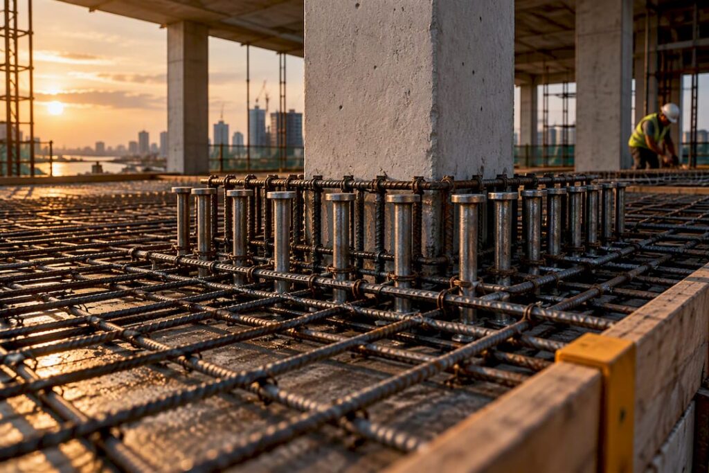
Punching shear is the brittle failure mode at slab-column connections, and it governs many flat slab and footing designs before flexure ever gets a chance to. The direct path to a safe design is straightforward: calculate vEd at the column face (u0) and at the basic control perimeter u1, located 2d out, then compare both against vRd,max and vRd,c under EN 1992-1-1, applying the Singapore National Annex where it modifies the base clauses. If vEd exceeds vRd,c at u1, you size shear reinforcement or extend the perimeter until it does not.
TL;DR:
- Punching shear typically governs internal, edge, or corner columns supporting flat slabs, especially with long spans, thin slabs, or heavy concentrated loads.
- The control perimeter is drawn at two slab depths from the loaded face, with vEd checked against vRd,max at the face and vRd,c at the perimeter to determine if reinforcement or slab thickening is needed.
- Reinforcement sizing should only proceed if vEd exceeds vRd,c but remains below twice vRd,c, avoiding unnecessary reinforcement or slab size increase.
- Real system effects can boost punching resistance by up to 48 percent, but assumptions about continuity and boundary restraints must be verified in the actual layout.
- Software checks often fail when perimeter assumptions don’t match the actual geometry, underscoring the importance of manual verification before approval.
Table of Contents
- When Does Punching Shear Design Actually Govern?
- What Are the Control Perimeters u0, u1, and uout?
- How Do You Calculate Punching Shear Step by Step?
- Sizing Punching Shear Reinforcement to EC2 6.52
- Where Do Software Punching Checks Go Wrong?
- Worked Example: Internal Column Punching Check
- How Stellar Structures Approaches Punching Shear Checks
- Why Durability Matters for Punching Shear Reinforcement
- Inspecting and Maintaining Punching Shear Zones
- How Does Eurocode Compare With ACI and Other Codes?
- How Slab Thickness and Concrete Grade Change Punching Capacity
- How Axial Load Changes the Punching Shear Check
- What the Research Says About the Future of Punching Shear Practice
- Get Punching Shear Checks and Authority Submissions Handled Together
- Sources
- FAQ
When Does Punching Shear Design Actually Govern?
Punching shear controls the design in a narrower set of situations than most engineers assume at first pass, but those situations show up constantly in real projects. Internal columns supporting flat slabs are the classic case, especially where spans are generous and slab thickness has been trimmed for headroom or cost. Edge and corner columns are riskier per unit of shear demand because they have less perimeter to spread the load across. Pad footings under heavy point loads and slabs carrying concentrated equipment loads follow the same physics.
The failure mode itself is what makes early checking non-negotiable. Punching shear failure is sudden and largely without warning, unlike flexural failure, which telegraphs itself through visible cracking and deflection first.
- Internal columns in flat plates with thin slabs or long spans
- Edge and corner columns with reduced control perimeters
- Pad footings and isolated foundations under high axial load
- Slabs with concentrated point loads from machinery, storage racks, or transfer structures
Research from RWTH Aachen shows that system effects such as compressive membrane action can raise punching resistance by 12 to 48 percent compared to isolated test specimens. That’s a real margin, but it comes from continuity and boundary restraint you should not assume exists without checking the actual slab layout.
What Are the Control Perimeters u0, u1, and uout?
Punching shear calculation lives and dies on where you draw these perimeters, so get the geometry right before you touch a formula. The Concrete Centre’s guidance on Eurocode 2 confirms the basic control perimeter u1 sits at a distance of 2d from the loaded face, rounded to minimize its length, with vEd checked at both u0 (the column face) and u1.
- u0 traces the column or loaded area perimeter directly; for a rectangular column it’s simply the sum of the four faces.
- u1 is 2d out from u0, with rounded corners for rectangular columns rather than sharp right angles, which shortens the perimeter slightly and matters for tight column grids.
- Edge and corner columns use a truncated u1 that excludes the portion beyond the slab edge, which concentrates stress and typically governs before internal columns do.
- Effective depth d is taken as the mean of the two orthogonal effective depths (dx and dy), since punching resistance depends on both reinforcement directions.
- β accounts for moment transfer at the connection; unbalanced moment from lateral load or uneven spans increases the effective shear stress well beyond VEd/u·d alone.
How Do You Calculate Punching Shear Step by Step?
Run the checks in a fixed sequence so nothing gets skipped, because the most common design error is jumping straight to reinforcement sizing before confirming vRd,max isn’t already exceeded at the column face.
Step 1: Establish VEd. Take the design shear force transferred to the column, typically from a grillage or finite element model, and confirm it reflects the tributary area correctly rather than a lump-sum reaction.
Step 2: Select β. For an internal column with no significant moment transfer, β is often taken close to 1.15 per the EC2 default for approximate analysis; for edge and corner columns, or where lateral loads introduce real moment transfer, β climbs and must be calculated explicitly using the eccentricity of load relative to the perimeter’s centroid.
Step 3: Calculate vEd at u0. vEd = β VEd / (u0 · d). Compare this against vRd,max, the crushing limit near the column face. If vEd exceeds vRd,max here, no amount of reinforcement fixes it. You need a bigger column, a thicker slab, or a higher concrete strength class.
Step 4: Calculate vEd at u1. Same formula, now using u1’s perimeter length. Compare against vRd,c, the concrete’s unreinforced punching resistance, which depends on fck, the longitudinal reinforcement ratio ρl, and d.
Step 5: Apply the national check. Singapore’s amendment and equivalent national annexes require vEd ≤ 2 vRd,c at u1 as a practical ceiling on how far reinforcement can compensate for inadequate concrete capacity.
Step 6: Decide on reinforcement. If vEd at u1 sits between vRd,c and 2 vRd,c, size shear reinforcement. If vEd already exceeds 2 vRd,c, revisit the slab thickness or column size instead of trying to reinforce your way out.
Where eccentricity is small and the layout is regular, a conservative default β value avoids a full moment-transfer calculation. Once eccentricity is significant, treat that shortcut as unsafe and calculate β properly.
Sizing Punching Shear Reinforcement to EC2 6.52
Once vEd at u1 sits above vRd,c, you’re sizing reinforcement, and Singapore’s amendment changes the numbers you plug in. The Singapore National Annex modifies EC2 Expression 6.52 for vRd,cs, defines fywd,ef as 250 + 0.25d (capped at fywd), and recommends a kmax value of 1.5 for the national ceiling on total resistance.
- Calculate vRd,cs = 0.75 vRd,c + 1.5 (d/sr) Asw fywd,ef [1/(u1 d)] sinα, solving for the required Asw once the other terms are known.
- Confirm Asw meets the code minimum, Asw,min, so the reinforcement contributes meaningfully rather than sitting below the threshold where it’s assumed effective.
- Select bar sizes, typically H8 or H10 studs or links depending on spacing and cover, and check they fit within the slab’s available depth.
- Set radial spacing sr starting at 0.3d to 0.5d from the column face, with a practical maximum radial spacing near 0.75d.
- Set tangential spacing at no more than 1.5d inside u1 and no more than 2d outside it, extending reinforcement out to uout where vEd finally drops below vRd,c unreinforced.
Pro Tip: Radial stud rails around a circular or near-circular perimeter usually beat orthogonal link arrangements on cost and buildability when the column geometry allows it, since fabrication and placement are simpler than threading individual link sets through congested top and bottom mats.
Where Do Software Punching Checks Go Wrong?
Punching-check modules in tools like Tekla Structural Designer place perimeters at multiples of d automatically and apply a ΔV adjustment moving outward, which is convenient until the underlying assumptions don’t match your actual geometry.
- Verify the centroid used for moment transfer matches the real column position, not a default grid intersection.
- Confirm the software isn’t ignoring the unbalanced moment fraction at edge or corner columns.
- Check effective depth inputs reflect actual cover and bar layout, not a generic default.
- Review how the tool handles openings, column drops, and overlapping perimeters between closely spaced columns.
- Run one hand check at u1 for every critical column before trusting the batch output.
Worked Example: Internal Column Punching Check
Take a 400mm square internal column, slab depth giving d = 200mm, VEd = 950kN, fck = 32MPa, and ρl = 0.010.
- u0 = 4 × 400 = 1,600mm. u1 = perimeter at 2d (400mm) out, rounded corners: roughly 1,600 + 2π(400) ≈ 4,113mm.
- With β ≈ 1.15 for a regular internal column, vEd at u0 = 1.15 × 950,000 / (1,600 × 200) ≈ 3.42 N/mm². Compare against a typical vRd,max in the range of 4.5 to 5.0 N/mm² for this concrete class; the face check passes.
- vEd at u1 = 1.15 × 950,000 / (4,113 × 200) ≈ 1.33 N/mm². A typical vRd,c for fck = 32 and ρl = 0.010 lands near 0.60 to 0.65 N/mm², so vEd clearly exceeds vRd,c and reinforcement is required.
- Checking the national ceiling: 2 vRd,c ≈ 1.25 N/mm², and vEd at 1.33 N/mm² sits just above it, meaning reinforcement alone at u1 is marginal. In practice, this pushes the design toward a thicker slab, a slightly larger column, or reinforcement extended carefully with a rigorous rather than approximate β.
- If proceeding with reinforcement, solve Expression 6.52 for Asw using sr = 150mm (0.75d) and fywd,ef = 250 + 0.25(200) = 300 N/mm², then select H10 studs at the calculated spacing.
The step most engineers skip here is the 2 vRd,c ceiling check. Missing it produces a design that looks fine on the vRd,cs formula alone but violates the national limit on how much shear reinforcement can realistically achieve.
How Stellar Structures Approaches Punching Shear Checks
Stellar Structures runs structural and geotechnical design checks on flat slabs, transfer structures, and footings as part of its structural engineering consulting work in Singapore. In practice, that means confirming column drops, slab openings near columns, and construction-stage loading haven’t been left out of the model, alongside standard authority submission coordination. On sites near coastal or marine-adjacent conditions, durability provisions for shear reinforcement get extra scrutiny during these checks, since corrosion risk to studs and links compounds faster than to the main flexural steel.
Why Durability Matters for Punching Shear Reinforcement
Shear studs and links sit close to the slab surface near the column face, often with less concrete cover margin than main flexural bars because of congestion at the connection. That makes durability a design decision, not an afterthought bolted on at detailing stage.
Exposure class governs the minimum cover, and punching shear reinforcement in a car park deck exposed to de-icing salts or chloride-laden runoff needs the same exposure-class cover as the surrounding structure, never a reduced value just because it’s a secondary reinforcement layer. Where studs are cast into congested zones with tight bar spacing, actual achieved cover often falls short of the specified minimum unless spacers and installation sequencing are checked on site, not just on the drawing.
Stainless or galvanized studs are worth specifying in marine-adjacent or industrial sites where routine inspection access to the connection is limited after construction, since replacing corroded shear reinforcement inside a finished slab is close to impossible without extensive and disruptive remedial work. Standard carbon steel studs remain appropriate for typical internal, non-aggressive exposure classes, where cover and concrete quality alone provide adequate protection over the design life.
Detailing also affects durability indirectly: tighter radial and tangential spacing packs more steel into a smaller volume of concrete, which can reduce compaction quality around each stud if vibration access is poor. Specifying self-compacting concrete or adjusting the spacing envelope slightly wider, within code limits, sometimes solves a durability problem that looks like a reinforcement problem on paper.
Inspecting and Maintaining Punching Shear Zones
Punching shear connections are largely invisible once the slab is cast, which is exactly why periodic structural inspection protocols treat them as a priority zone rather than a routine sweep. Visible warning signs, when they do appear, tend to show up as radial cracking on the soffit around the column, or as a faint circular crack pattern tracing roughly where the control perimeter sits.

Under Singapore’s BCA Periodic Structural Inspection regime, inspectors pay particular attention to slab-column connections in older flat slab buildings, especially where original design margins were tighter than current code would allow. A BCA Periodic Structural Inspection typically flags any soffit cracking near columns for closer assessment rather than dismissing it as cosmetic, because punching shear distress rarely announces itself gradually the way flexural cracking does.
Maintenance access matters at the design stage too. Connections buried inside finished ceilings or behind mechanical services are harder to inspect later, so specifying an accessible inspection point, or at minimum documenting stud rail locations clearly in as-built records, saves considerable time when a future inspection needs to confirm what reinforcement is actually there. Load changes over a building’s life, added mechanical plant, a change of use to heavier storage, are the other trigger worth flagging: any load increase near a column should prompt a fresh punching shear check against the original design assumptions, not an assumption that the original margin still holds.
How Does Eurocode Compare With ACI and Other Codes?
EN 1992-1-1’s control perimeter approach is not the only way to check punching shear, and the differences matter if you’re working across jurisdictions or reviewing a design produced under a different code.
ACI 318 uses a critical section at d/2 from the column face rather than Eurocode’s 2d perimeter, and its concrete shear strength formula runs on a different basis entirely, tied to concrete compressive strength and column geometry ratios rather than the reinforcement-ratio-dependent vRd,c formula in EN 1992-1-1. The practical effect is that ACI’s critical perimeter sits much closer to the column, which changes both the calculated perimeter length and the resulting stress, so a direct numerical comparison between an EC2 and an ACI check on the same slab rarely lines up without careful unit and definition tracking.

British Standard BS 8110, the predecessor most Commonwealth-trained engineers still recognize, used a similar 1.5d perimeter concept rather than EC2’s 2d, with its own concrete shear stress table keyed to reinforcement percentage and concrete grade. Engineers moving from BS 8110 practice to EN 1992-1-1 sometimes carry over intuitions about perimeter distance that don’t transfer directly, which is a common source of hand-check discrepancies during design review.
None of these codes is simply “more conservative” across the board. Eurocode’s 2 vRd,c national ceiling on reinforced capacity has no direct ACI equivalent, while ACI’s stud rail provisions for shear reinforcement follow different spacing and layout rules than EC2’s radial and tangential limits. For a project designed to EN 1992-1-1 with the Singapore National Annex, the governing document is that annex and the base code, not an ACI cross-check, but understanding where the frameworks diverge helps when reviewing imported designs or working with international consultants.
How Slab Thickness and Concrete Grade Change Punching Capacity
Slab thickness drives punching shear capacity through two separate mechanisms, and conflating them leads to under-designed connections even when the arithmetic looks correct.
The first mechanism is direct: increasing d lengthens u1, since the perimeter sits at 2d from the column face, so thicker slabs distribute the same VEd over a longer perimeter and lower vEd automatically. The second mechanism is that vRd,c itself carries a depth-dependent term that increases resistance per unit area as d grows, within EC2’s formula for concrete punching resistance. Together, these mean a modest increase in slab thickness, say 25mm, can shift a marginal fail into a comfortable pass without touching reinforcement ratio or concrete grade at all.
Concrete strength class works differently. Raising fck increases vRd,c and vRd,max, but the relationship is not linear, and pushing to a much higher grade purely to solve a punching shear problem often costs more than adding local slab thickening or a column head instead. Higher grade concrete does help more where the face check at u0 against vRd,max is the binding constraint, since that limit scales more directly with concrete strength than the u1 check does.
Reinforcement ratio ρl also feeds into vRd,c, but it’s a secondary lever compared to d. Doubling the flexural reinforcement ratio near a column produces a much smaller punching capacity gain than a modest increase in slab depth, which is worth remembering before specifying congested top steel purely to chase a punching shear pass. The most cost-effective sequence for a marginal check, in most cases, is thickness first, concrete grade second, and reinforcement ratio only as a fine-tuning step.
How Axial Load Changes the Punching Shear Check
Axial load’s role in punching shear design is often underappreciated because VEd already captures the vertical shear transfer, but the moment transfer component, folded into β, is where axial load and lateral load interact in ways that catch inexperienced reviewers off guard.
For a column carrying significant unbalanced moment, from an asymmetric span layout, a lateral load system, or a transfer structure irregularity, the eccentricity of that moment relative to the control perimeter’s centroid increases the effective shear stress well beyond what VEd alone would suggest. A column with modest axial load but high moment transfer can govern punching shear before a heavily loaded but well-balanced internal column does, which is exactly the scenario a default β shortcut misses.
Foundations add a further wrinkle: for pad footings, the net upward soil pressure under the footprint of the control perimeter can be deducted from VEd, since that pressure isn’t transferred through the punching mechanism the same way slab load is. Skipping this deduction produces an artificially conservative, sometimes needlessly expensive, footing design. Where axial load is transferred through a column with a significant change in section, a transfer level or podium column landing on a smaller column below, both perimeters need checking independently, since the smaller section below often governs even though it carries the same nominal axial load.
What the Research Says About the Future of Punching Shear Practice
System effects like compressive membrane action genuinely raise capacity beyond the isolated-specimen basis EC2’s formulas were calibrated against, and the 12 to 48 percent margins RWTH Aachen documented are real. That said, code equations remain the safe default for routine work. Reserve rotation-based or system-level analysis for critical infrastructure, and document every departure from the simplified perimeter method for peer review.
— Aman
Get Punching Shear Checks and Authority Submissions Handled Together
Getting the calculation right is only half the job in Singapore. The design also has to clear BCA review, and that’s where a lot of otherwise sound punching shear work stalls on submission formatting or documentation gaps. Stellar Structures runs structural design checks and manages the authority submission process as one coordinated engagement, so the calculations that satisfy EN 1992-1-1 and the Singapore National Annex arrive in front of the reviewing authority already packaged the way BCA expects to see them.

That combination matters most at slab-column connections, transfer structures, and footing designs where punching shear is the binding check, because a reviewer’s first question is usually whether the control perimeter and reinforcement detailing match what’s shown in the drawings. Stellar Structures’ structural and geotechnical engineering consultation work covers exactly that gap between a correct hand calculation and a submission-ready package. If a project has a punching-shear-critical connection you’d like a second set of eyes on before it goes to authority review, get in touch through the services page and describe the column layout and loading, and the team can scope a design check or submission support engagement from there.
Sources
- Punching shear — The Concrete Centre (Eurocode guidance)
- Punching shear in flat slab systems – Experimental quantification of unconsidered system influences (RWTH Aachen)
- Punching shear check fundamentals | Tekla Structural Designer documentation
FAQ
What Is Punching Shear?
Punching shear is a localized, brittle failure mode where a column or concentrated load punches through a slab or footing along a roughly conical or pyramidal surface around the loaded area. It differs from beam shear because the failure surface wraps around the load on all sides rather than running along a single line, and EN 1992-1-1 checks it at defined control perimeters rather than at a single critical section.
How Do You Calculate Punching Shear in a Footing?
Calculate VEd as the column load minus any net upward soil pressure acting within the control perimeter’s footprint, since that pressure doesn’t transfer through the punching mechanism. Then check vEd = β VEd / (u · d) at both u0 and u1 against vRd,max and vRd,c the same way as for a slab, noting that many codes restrict or prohibit shear reinforcement in isolated foundations, so a thickness or size adjustment is often the only remedy.
How Do You Calculate the Punching Shear Capacity of a Slab?
Punching shear capacity without added reinforcement, vRd,c, depends on concrete strength class fck, the longitudinal reinforcement ratio ρl, and effective depth d, calculated per EN 1992-1-1’s formula for concrete punching resistance. Where that capacity is insufficient, sizing shear reinforcement follows EC2 Expression 6.52, adjusted for Singapore’s fywd,ef and kmax values under the National Annex.
Does Stellar Structures Perform Punching Shear Design Checks?
Stellar Structures provides structural and geotechnical design checks for flat slabs, transfer structures, and footings, including punching shear verification to EN 1992-1-1 and the Singapore National Annex. Pricing for this service is available on request through the firm’s services page.
Recommended
- How to Increase Floor Load Capacity in Existing Singapore Commercial Buildings
- A Comprehensive Guide to Vibration Control in Singapore’s Buildings
- Structural Design Requirements for Modern Data Centers in Singapore
- Acoustic and Vibration Isolation in Commercial Structural Design