




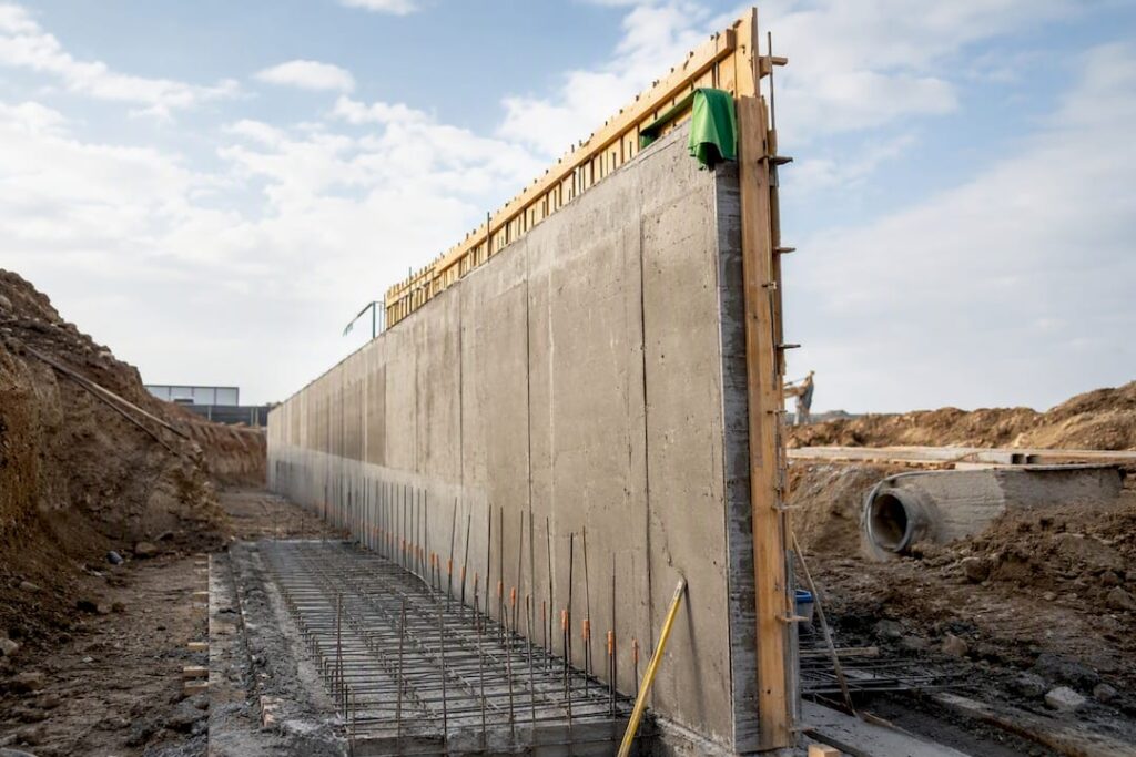
A compliant retaining wall design must document five things: verified geotechnical parameters, a lateral earth pressure diagram appropriate to the wall’s flexibility, sliding/overturning/bearing checks that clear code-minimum factors of safety, a reinforcement schedule tied to those pressures, and a drainage detail that removes hydrostatic load before it ever reaches the stem. Excavations deeper than a certain depth trigger additional ERSS documentation, instrumentation, and contingency planning before a permit reviewer will sign off.
TL;DR:
- Depth and type of excavation affect ERSS documentation, instrumentation, and contingency planning, especially beyond 6 meters, due to increased risk.
- Groundwater level, soil stratigraphy, and strength properties must be verified on-site with boreholes spaced according to project risk and complexity.
- Static earth pressure methods like Rankine are suitable for simple, vertical-back walls, while Coulomb or Mononobe-Okabe are needed for inclined backfill or seismic cases.
- Drainage design is critical; proper subdrains, weep holes, and granular backfill prevent hydrostatic pressure buildup and extend wall longevity.
- Early coordination of geotechnical, structural, and construction planning ensures durability and prevents costly failures related to drainage, stability, or construction sequence.
Table of Contents
- What Are the Main Types of Retaining Walls and How Do You Choose One?
- What Geotechnical Data Does Retaining Wall Design Require?
- Which Earth Pressure Method Should You Use: Rankine, Coulomb, or Mononobe-Okabe?
- How Do You Check Sliding, Overturning, and Bearing Capacity?
- How Do You Design Drainage to Prevent Retaining Wall Failure?
- How Do You Convert Earth Pressure Into Structural Reinforcement?
- What Construction Sequence and QC Checks Protect the Design?
- Worked Example: Designing a Cantilever Retaining Wall Step by Step
- What ERSS and Monitoring Requirements Apply to Deep Excavations?
- How Does Seismic Loading Change Retaining Wall Design?
- What Sustainability Factors Matter in Retaining Wall Design?
- How Do Maintenance Needs Differ Across Retaining Wall Types?
- Which Codes and Standards Govern Retaining Wall Design?
- What Are the Most Common Retaining Wall Failure Modes?
- Why Integrated Design Review Beats Siloed Retaining Wall Engineering
- How Stellar Structures Supports Retaining Wall Projects in Singapore
- Sources
What Are the Main Types of Retaining Walls and How Do You Choose One?
Wall selection is a constrained optimization problem, not a preference exercise. The site geometry, groundwater table, adjacent structures, and available footprint eliminate most options before cost enters the conversation at all.
Gravity walls rely on mass alone to resist overturning and sliding. They work well for low walls where plain concrete or masonry is cheaper than reinforcing steel, but the base width required scales fast with height, which kills them on tight urban lots.
Cantilever walls use a reinforced concrete stem and base slab, letting the weight of backfill on the heel do the resisting work. This is the default choice for walls between 3 and 7 meters where you have room for a base but not for a gravity mass. Most of the worked calculations in this article assume a cantilever configuration because it is the most common permit submission type for mid-rise and landed projects.
Embedded walls (sheet-pile, contiguous bored pile, diaphragm) get driven or cast before excavation begins, then act as both temporary earth support and sometimes permanent structure. These dominate deep excavation and basement work where space for a spread footing does not exist.
Anchored walls add ground anchors or tiebacks to an embedded wall, extending achievable height and reducing bending moment in the wall itself. Useful when passive resistance in front of the toe is limited or when deflection control near adjacent buildings is strict.

Segmental and mechanically stabilized earth (MSE) walls use reinforced soil with geogrid layers behind a modular facing. They are efficient for large landscaped slopes and highway embankments but need substantial reinforced-zone width behind the face, roughly 0.7 to 1.0 times the wall height.
Gabion walls are semi-flexible, permeable gravity structures. They tolerate differential settlement better than rigid concrete and drain almost by default, which makes them a strong fit for slope stabilization on variable fill.
Selection criteria in practice come down to a short checklist:
- Available base width behind or in front of the wall face
- Groundwater table elevation relative to the wall toe
- Tolerable lateral deflection, especially near existing foundations
- Whether the wall is temporary (construction-stage) or permanent
- Access for compaction equipment during backfilling
A 2025 review of earth retaining system selection-11) identifies eight distinct selection bases, including cost, height, base width, alignment, and flexibility, and notes that geometry optimization tools like relief shelves can materially cut lateral earth pressure and the resulting material quantity. Rigid systems (gravity, cantilever) suit stable native ground with predictable strength; flexible systems (sheet-pile, anchored, gabion) suit sites where some deformation is acceptable or where soil conditions are too variable to trust a rigid footing.
What Geotechnical Data Does Retaining Wall Design Require?
No stability check means anything without verified soil parameters, and this is where a surprising number of preliminary designs fall apart. Assumed soil values from a nearby project are not a substitute for site-specific data, especially in variable fill or reclaimed ground.
A minimum geotechnical investigation for retaining wall design should include borehole logs capturing stratigraphy well below the founding level, or to a competent bearing stratum, whichever governs.
2. Unit weight (γ) for each soil layer, both bulk and submerged where groundwater is present.
3. Effective friction angle (φ’) and cohesion (c’) derived from triaxial or direct shear tests, not assumed from a generic soil classification table.
4. Permeability (k) values to assess drainage design and whether hydrostatic pressure can realistically build up behind the wall.
5. Groundwater table elevation, seasonal variation if data exists, and any perched water conditions in layered fill.
6. SPT N-values with correlations to relative density and, cautiously, to friction angle for granular soils where direct shear testing was not performed.
7. CPT data where available, offering continuous stratigraphic resolution that boreholes at wide spacing will miss.
Borehole spacing needs to tighten as risk increases. For routine cantilever walls, typical spacing along the alignment is on the order of tens of meters, with at least one borehole at each geometry change. For excavations exceeding 6 meters where ERSS provisions apply, spacing should tighten considerably, and supplementary boreholes at the toe and heel of each major structural element help catch localized soft pockets that a coarse grid would miss entirely.
Interpreting stratigraphy correctly matters most at two points: toe embedment depth, where you need confidence in the bearing stratum’s actual strength rather than an assumed uniform layer, and basal heave potential in soft clay, where a thin sand lens beneath a clay plug can trigger unexpected uplift during excavation.
Converting lab results to design values is not a straight pass-through. Apply partial factors to characteristic soil strength values per the applicable code (Eurocode 7’s material factor approach, for instance, typically divides tan φ’ by 1.25 and c’ by 1.25 for the fundamental combination), and always cross-check derived design values against regional correlation charts before locking them into a calculation package. A firm’s geotechnical site investigation guidance is often the difference between a design that survives peer review on the first pass and one that gets bounced back with parameter queries.
Which Earth Pressure Method Should You Use: Rankine, Coulomb, or Mononobe-Okabe?
The short answer: Rankine for simple vertical-back walls with horizontal backfill and no wall friction consideration; Coulomb when the wall back is inclined, the backfill slopes, or wall friction meaningfully affects the resultant; Mononobe-Okabe when seismic loading applies.
Rankine theory assumes a frictionless wall interface and a vertical back, which simplifies the math considerably but can understate or overstate pressure depending on actual wall geometry. It remains the default teaching method and works fine for most cantilever wall stems, where the assumed failure plane behind a vertical virtual back closely matches reality.
Coulomb theory accounts for wall friction (δ), a battered or inclined back face, and sloped backfill, which makes it more accurate for gravity walls, MSE structures, and any wall geometry that deviates from Rankine’s simplifying assumptions. The trade-off is a more involved calculation and a coefficient that is more sensitive to input assumptions on friction angle.
Choosing between active, at-rest, and passive pressure states depends entirely on how much the wall is free to move:
- Active pressure (Ka) applies when the wall can deflect enough to mobilize the full shear strength of the retained soil, typically a lateral movement of 0.1 to 0.5 percent of wall height for granular backfill.
- At-rest pressure (Ko) governs when the wall is rigidly restrained, such as basement walls braced top and bottom, where deflection is essentially prevented.
- Passive pressure (Kp) develops when the wall moves into the soil, relevant on the toe side for sliding resistance, but it requires far greater movement to fully mobilize than active pressure does, which is why many designers apply a reduction factor rather than assuming full Kp is available.
Partially restrained walls, common in basement construction where a floor slab braces the top before backfilling is complete, sit somewhere between Ka and Ko. Treating them as fully active without justification is a common source of under-design.
Pro Tip: Never assume full passive resistance is available at the toe unless you have confirmed the soil in front of the wall will not be excavated, disturbed, or removed at any point during the structure’s service life. Contractors trenching for future utilities in front of a retaining wall toe have quietly turned “adequate” designs into failures.
Surcharge loads (from adjacent footings, traffic, or stockpiled material) add a uniform or triangular pressure increment on top of the soil-derived pressure, calculated using the same Ka or Kc coefficient applied to the equivalent soil height of the surcharge. Hydrostatic pressure, where drainage fails or was never designed in the first place, adds a separate triangular distribution using the unit weight of water rather than soil, and it can easily double the total lateral load on an undrained wall.
Seismic loading calls for the Mononobe-Okabe method, a pseudo-static extension of Coulomb theory that adds a horizontal (and sometimes vertical) seismic coefficient to the driving force. This becomes the governing case in regions with meaningful seismic hazard, and it is discussed further in the seismic design section below.
How Do You Check Sliding, Overturning, and Bearing Capacity?
These three checks are the backbone of every retaining wall submission, and a design that passes earth-pressure calculations but fails any one of them is not a design at all, it’s a draft.
- Sliding. Compare the sum of resisting forces (friction at the base, plus passive resistance if reliably available) against the total horizontal driving force from active earth pressure and surcharge. Target factor of safety is typically 1.5 for static cases, dropping to around 1.1 to 1.2 under seismic combinations depending on the governing code.
- Overturning. Take moments about the toe, comparing the resisting moment (from wall self-weight and soil above the heel) against the overturning moment from lateral pressure. A factor of safety of 2.0 is the common static target, though some codes now express this as a limit on eccentricity instead of a direct FOS ratio.
- Bearing capacity. Compute the resultant vertical force location and check that it falls within the middle third of the base (limiting eccentricity, e ≤ B/6) to avoid tension at the heel. Then verify the maximum toe pressure against the allowable bearing capacity from the geotechnical report, applying an appropriate factor of safety, usually 2.5 to 3.0 for static loading.
Combine load cases deliberately rather than checking a single “typical” scenario. Minimum gravity load (empty or partially backfilled, worst case for overturning and sliding) and maximum lateral load (fully backfilled, saturated, with full surcharge) rarely produce the governing result from the same combination, and permit reviewers expect both documented separately.
When a check fails, the corrective options follow a predictable hierarchy: widen the base slab first (cheapest structurally, though it costs footprint), add a shear key beneath the base to mobilize additional passive resistance against sliding, extend the heel to add more resisting weight for overturning, or introduce ground anchors where footprint constraints make a wider base impossible. Improving drainage to eliminate hydrostatic surcharge is often the single cheapest fix available, since a wall failing by a narrow margin frequently only fails because someone assumed the backfill would stay dry.
Pro Tip: Document every load combination and its governing FOS explicitly in the submission package, even the ones that pass comfortably. Reviewers spend less time on a design that shows its work than one that only presents the final “OK” line.
How Do You Design Drainage to Prevent Retaining Wall Failure?
Drainage failure is the most commonly cited cause of retaining-wall distress in professional practice, and it is almost entirely preventable with correct detailing at the design stage rather than expensive intervention later. A structural engineering analysis of retaining wall essentials identifies inadequate drainage as the dominant failure driver, ahead of undersized reinforcement or poor bearing capacity assessment.
The core drainage components every design should specify:
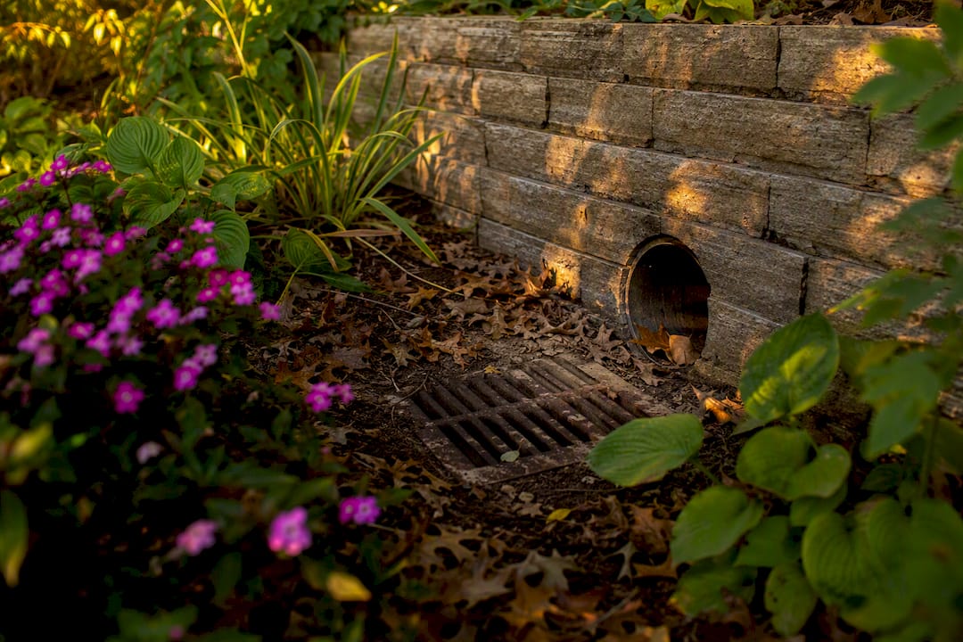
- A perforated subdrain pipe at the base of the wall, wrapped in geotextile filter fabric, sloped to daylight or connected to a positive outfall.
- A free-draining granular zone directly behind the stem, typically 300 to 450 millimeters wide, using aggregate with less than 5% fines content to prevent clogging.
- Weep holes through the stem at 1 to 2 meter horizontal spacing, staggered vertically, sized around 75 to 100 millimeters diameter, as a backup outlet if the subdrain becomes compromised.
- A geotextile separator between the granular drainage zone and native or compacted backfill, preventing fines migration into the free-draining aggregate over time.
- A capping layer of low-permeability fill or surface grading that sheds surface water away from the wall crest rather than letting it pond and infiltrate.
Backfill specification matters as much as the drainage hardware itself. Specify a granular backfill with a plasticity index near zero and fines content capped low enough to remain free-draining, compacted in lifts no thicker than 200 to 300 millimeters using appropriate vibratory or plate compaction depending on proximity to the wall. Over-compaction directly against a young concrete stem can actually increase lateral pressure beyond design assumptions, so compaction equipment and lift thickness near the wall face should be specified separately from the bulk of the backfill zone. Document acceptance testing with nuclear density gauge or sand-cone results at a defined frequency per lift, tied to a minimum percentage of standard Proctor density.
Pro Tip: Specify a maintenance access point, even a simple removable grate over the subdrain outfall, at the design stage. A drainage system nobody can inspect or clear of debris after five years is a drainage system that will eventually fail exactly the way the original design was meant to prevent.
How Do You Convert Earth Pressure Into Structural Reinforcement?
Once the earth pressure diagram and stability checks are settled, the geotechnical problem becomes a structural one: converting a triangular (or trapezoidal, with surcharge) pressure distribution into bending moment and shear demand on the stem and base slab.
- Stem design. Treat the stem as a vertical cantilever fixed at the base, with the earth pressure diagram producing a moment that increases toward the base. Maximum moment occurs at the stem-to-base connection, which is why reinforcement here is typically the heaviest in the entire structure and why construction joints at this location deserve particular scrutiny for shear transfer.
- Base slab design. The heel and toe act as cantilevers off the stem, each loaded by soil weight and bearing pressure respectively, in opposite directions. The heel typically carries downward soil load plus any surcharge, while the toe resists upward bearing pressure, and both need independent moment and shear checks.
- Applying partial factors. Codes following the limit state approach (Eurocode 2 and its national annexes, or equivalent ACI 318 load and strength reduction factors) require factored loads on the demand side and reduced material strengths or capacity reduction factors on the resistance side. Do not mix a working-stress geotechnical check with a limit-state structural check without clearly tracking which factors apply where.
- Rebar layout. Vertical reinforcement in the stem typically concentrates near the earth-facing tension zone, with horizontal temperature and shrinkage steel at code-minimum ratios (often around 0.15 to 0.20 percent of gross cross-section for exposed exterior faces). Base slab reinforcement runs both ways, with the heel’s top reinforcement and toe’s bottom reinforcement sized independently based on their respective moment diagrams.
- Anchorage and lap lengths. The stem-to-base dowel connection needs development length sufficient to transfer the full design moment across the construction joint, calculated per the governing code’s development length provisions, not assumed from a rule-of-thumb multiplier without checking bar size and concrete strength.
- Crack control and cover. Buried concrete faces in contact with soil, particularly in aggressive or chloride-bearing ground, typically require increased cover, often 50 to 75 millimeters versus 40 millimeters for a standard exterior face, along with tighter crack-width limits to protect durability over a multi-decade service life.
The geotechnical and structural sides of this problem are not independent. If the structural design assumes passive resistance at the toe to reduce required base width, that assumption has to be justified geotechnically, confirming the soil in front of the toe will remain in place and undisturbed for the wall’s service life. A design that quietly relies on optimistic passive pressure while the geotechnical report never confirmed it is a common gap between disciplines that shows up during independent design checks.
What Construction Sequence and QC Checks Protect the Design?
A retaining wall design’s calculations only hold if construction actually follows the sequence and quality standards the design assumed. Deviating from the assumed excavation sequence is one of the more common ways a theoretically sound design fails in the field.
For a cantilever wall, the typical safe sequence runs: excavate to formation level in controlled stages, place blinding concrete, install base slab reinforcement and formwork, cast the base, then form and cast the stem once the base has achieved sufficient strength for dowel continuity, followed by backfilling in specified lifts only after the stem has cured to design strength.
For sheet-pile or embedded walls supporting deeper excavations, staged excavation with temporary strutting or ground anchors installed progressively as excavation proceeds is essential; removing more soil than the temporary bracing at that stage can support is a leading cause of wall movement incidents. Each stage should have a defined maximum excavation depth before the next level of struts or anchors goes in.
Quality control records that protect the design intent include:
- Compaction test results (density and moisture content) for every backfill lift, referenced against the specified Proctor density.
- Sheet-pile installation records, including press-in force or driving energy and interlock continuity checks, since declutched interlocks are a recognized ground-loss risk in urban excavations.
- Concrete quality assurance: slump tests, cylinder or cube compressive strength results, and cover checks before backfilling conceals the structure.
- As-built survey confirming wall alignment, base level, and any deviation from design geometry that might affect the pressure or stability calculations.
Common field pitfalls worth flagging explicitly: omitting the subdrain because it “wasn’t in the way” during excavation, over-compacting backfill directly against a green concrete stem, and treating sheet-pile interlock continuity as a given rather than a verified record. Each of these has a straightforward remedy if caught early (reinstate the drain before backfilling completes, adjust compaction equipment near the face, re-drive or grout a suspect interlock) but becomes far more expensive once the wall is backfilled and the problem is hidden.
Worked Example: Designing a Cantilever Retaining Wall Step by Step
This example walks a 4.5 meter cantilever wall through the full sequence, from geometry assumptions to reinforcement sizing, using representative parameters typical of a medium-dense sandy fill.
Step 1: Establish geometry and geotechnical inputs. Assume a stem height of 4.5 meters, base slab thickness of 450 millimeters, total wall height (including base) of 4.95 meters, base width of 3.0 meters (toe 0.8 m, heel 1.7 m, stem thickness 0.5 m at base). Backfill unit weight γ = 18 kN/m³, effective friction angle φ’ = 32°, no cohesion assumed for the granular backfill, and groundwater table well below founding level so no hydrostatic component applies in this case.
Step 2: Calculate active earth pressure coefficient. Using Rankine theory for this vertical-back, horizontal-backfill case: Ka = tan²(45° − φ’/2) = tan²(45° − 16°) = tan²(29°) ≈ 0.307.
Step 3: Compute the lateral pressure diagram and resultant. Maximum pressure at the base of the virtual back (height 4.95 m): p = Ka × γ × H = 0.307 × 18 × 4.95 ≈ 27.4 kN/m². Total resultant force (triangular distribution) per meter run: Pa = ½ × 27.4 × 4.95 ≈ 67.8 kN, acting at H/3 = 1.65 m above the base.
Step 4: Check sliding. Resisting force from base friction: assume a coefficient of friction (tan δ) of 0.5 against the founding soil, with total vertical load (wall self-weight plus soil above heel) estimated at approximately 195 kN per meter run. Friction resistance ≈ 0.5 × 195 = 97.5 kN. FOS against sliding = 97.5 / 67.8 ≈ 1.44, which sits below a common 1.5 static target, indicating a shear key or wider heel would be a reasonable next iteration.
Step 5: Check overturning. Resisting moment from self-weight and soil about the toe, estimated at roughly 285 kN·m per meter run, against the overturning moment from Pa: 67.8 × 1.65 ≈ 111.9 kN·m. FOS against overturning = 285 / 111.9 ≈ 2.55, comfortably clearing the 2.0 target.
Step 6: Check bearing and eccentricity. With total vertical load of 195 kN and net moment about the base centerline calculated from the resisting and driving moments, the resultant location falls within the middle third of the 3.0 meter base, confirming no heel tension and a manageable toe pressure well under the geotechnical report’s allowable bearing capacity.
Step 7: Derive stem reinforcement. Maximum stem moment at the base of the stem uses the pressure diagram over the exposed stem height (4.5 m), giving a factored design moment that sizes the main vertical tension reinforcement on the earth-facing side, typically working out to moderate bar sizes at 150 to 200 millimeter spacing for a wall in this height range, subject to the specific code’s load and strength reduction factors.
| Parameter | Value |
|---|---|
| Stem height | 4.5 m |
| Total wall height (with base) | 4.95 m |
| Base width | 3.0 m |
| Backfill unit weight (γ) | 18 kN/m³ |
| Friction angle (φ’) | 32° |
| Active pressure coefficient (Ka) | 0.307 |
| Resultant lateral force (Pa) | 67.8 kN/m |
| FOS against sliding | 1.44 |
| FOS against overturning | 2.55 |
The governing weakness in this iteration is sliding, not overturning or bearing, which is common for granular backfill on moderate-friction founding soil. The practical fix, adding a shear key 300 to 400 millimeters deep beneath the base, mobilizes additional passive resistance and typically pushes the sliding FOS comfortably past 1.5 without changing the overall footprint. This is exactly the kind of iteration free calculation tools handle quickly, though a hand check like this one remains the fastest way to sanity-test the software’s output before it goes into a submission package.
What ERSS and Monitoring Requirements Apply to Deep Excavations?
Excavations exceeding 6 meters in depth move into a different regulatory category entirely, requiring a formal Earth Retaining and Stabilizing Structures (ERSS) plan rather than a standard structural submission. URA guidance on earthworks confirms that excavation depth beyond 6 meters activates ERSS plan provisions, alongside separate limits like the 2.8 meter cap on visible boundary wall height for certain residential categories.
The BCA guideline on sheet-pile integrity requires ERSS plans for excavations beyond this depth to include risk-based mitigation categorized by installation risk level (low, medium, high), complete installation records covering penetration time and press-in force for sheet piles, and contingency measures specified by the qualified person for design, known as QP(D).
A defensible monitoring plan for deep excavation typically specifies:
- Inclinometers installed adjacent to the wall alignment at intervals tied to geological variability, tracking lateral deflection through the full depth of the retaining system.
- Piezometers to track groundwater response during dewatering or excavation, since unexpected pore pressure changes often precede visible wall movement.
- Settlement markers on adjacent structures and ground surface, read at a defined frequency that increases as excavation approaches critical stages.
- Action and trigger levels tied to specific deflection or settlement thresholds, with predefined contingency steps, halting excavation, backfilling a section, grouting a void, or installing additional piles, triggered automatically once a threshold is crossed rather than left to case-by-case judgment during a live excavation.
In Singapore’s regulatory structure, the QP(D) sets these design parameters, the QP for supervision (QP(S)) confirms field conditions match design assumptions, and the builder maintains installation and monitoring records. Coordinating ERSS design and clarifying when a geotechnical PE must be engaged during construction early in the project timeline avoids the common scenario where monitoring gets treated as an afterthought rather than a designed system.
How Does Seismic Loading Change Retaining Wall Design?
Seismic design shifts the governing earth pressure method from static Rankine or Coulomb theory to the Mononobe-Okabe pseudo-static approach, which adds horizontal (and optionally vertical) seismic coefficients derived from the site’s design ground acceleration to the driving force calculation.
The practical effect is a larger, and differently shaped, pressure distribution than the static case. Mononobe-Okabe pressure tends to act at a higher point on the wall than the static triangular distribution’s H/3 location, often approximated closer to 0.4H to 0.6H depending on the seismic coefficient magnitude, which increases the overturning moment disproportionately relative to the increase in total force.
Design codes typically permit reduced factors of safety under seismic load combinations compared to static cases, on the reasoning that a brief, rare seismic event does not carry the same long-term reliability requirement as sustained static load. A sliding FOS of 1.1 to 1.2 under seismic combination is common where a static case demands 1.5.
Walls retaining liquefiable soil need a separate check entirely. If the retained material or the founding soil is susceptible to liquefaction under design seismic shaking, both the earth pressure assumptions and the bearing capacity calculation change fundamentally, since liquefied soil behaves closer to a fluid than a frictional material and passive resistance at the toe may vanish exactly when it is needed most.
For regions with meaningful seismic hazard, wall flexibility becomes a genuine design variable rather than an afterthought. Rigid gravity and cantilever walls attract higher seismic force than flexible systems that can accommodate some deformation, which is part of why anchored and MSE systems sometimes outperform rigid alternatives in higher seismic zones, provided deflection tolerances at the site allow it.
What Sustainability Factors Matter in Retaining Wall Design?
Material selection carries the largest environmental footprint decision in most retaining wall projects, since concrete production accounts for a substantial share of embodied carbon in civil works generally. Reducing concrete volume through geometry optimization, rather than switching materials outright, is often the most achievable sustainability lever available to a practicing engineer.
Relief shelves, stepped-back stem geometry, and optimized batter angles reduce both the lateral earth pressure acting on the wall and the resulting concrete and reinforcement quantity needed to resist it, a relationship documented in the 2025 review of earth retaining system selection referenced earlier for wall type selection. A wall designed with a single unbroken face from base to crest is rarely the most material-efficient solution once height exceeds a few meters.
Recycled and supplementary cementitious materials, such as ground granulated blast furnace slag or fly ash replacing a portion of Portland cement content, reduce embodied carbon in the concrete mix without compromising structural performance when specified within tested proportions. Gabion and segmental systems also offer a sustainability advantage worth noting: their permeable construction reduces the drainage infrastructure needed compared to an impermeable concrete face, and their modular units can sometimes be sourced with recycled aggregate fill.
Long-term environmental performance matters as much as construction-stage impact. A wall that fails prematurely due to inadequate drainage or under-designed reinforcement generates a second full carbon cost through demolition and reconstruction, which makes durable, correctly detailed design a sustainability decision in its own right, not just a structural one. Specifying local materials where soil conditions allow, rather than importing select fill from distant quarries, further reduces the transport-related footprint of a typical retaining wall project.
How Do Maintenance Needs Differ Across Retaining Wall Types?
Rigid concrete walls, gravity and cantilever alike, need the least routine maintenance of any wall type provided drainage was correctly detailed at construction. Periodic inspection should focus on weep hole function, crack propagation at the stem-base joint, and any signs of soil loss at the toe from erosion or undermining.
Segmental and MSE walls require attention to facing unit displacement and joint integrity, since these systems rely on the geogrid reinforcement remaining properly connected to the facing over the structure’s service life. Vegetation growth through facing joints, while sometimes aesthetically desirable, can accelerate joint separation if roots penetrate deeply enough.
Gabion walls need periodic checks on wire mesh corrosion, particularly in coastal or chemically aggressive soil environments, since the mesh baskets rather than the stone fill provide structural continuity. Galvanized or PVC-coated mesh extends service life considerably compared to uncoated wire in aggressive exposure conditions, a consideration worth flagging for projects near marine or brackish environments.
Embedded and anchored walls carry the most durability-sensitive maintenance profile of the group, since corrosion of steel sheet piles or anchor tendons below grade is difficult to inspect visually and progresses invisibly until it becomes a serviceability or safety concern. Cathodic protection, corrosion allowance in section sizing, or protective coatings specified at design stage reduce this risk far more cost-effectively than any inspection regime applied after the fact.
Across every wall type, the single highest-value maintenance task is keeping drainage systems clear and functional. A subdrain outfall buried under years of landscaping mulch defeats the entire drainage design regardless of how well it was detailed on paper, which circles back to why specifying accessible maintenance points at the design stage pays off decades later.
Which Codes and Standards Govern Retaining Wall Design?
Retaining wall design sits at the intersection of geotechnical and structural codes, and the applicable set depends heavily on jurisdiction, though the underlying engineering principles remain consistent across most modern codes.
Eurocode 7 (EN 1997), together with its National Annex, governs geotechnical design including earth pressure calculation methods, partial factor application to soil strength, and limit state verification for sliding, overturning, and bearing. Eurocode 2 (EN 1992) covers the structural concrete design that follows, including reinforcement detailing, cover requirements, and crack control provisions referenced earlier in the reinforcement detailing section.
ACI 318, the American Concrete Institute’s structural concrete code, governs reinforced concrete retaining wall structural design in jurisdictions following US-derived standards, typically paired with geotechnical guidance from local building codes or ASCE standards for load combinations.
AS/NZS 4678 addresses earth retaining structures specifically in the Australian and New Zealand context, covering both geotechnical and structural aspects in a single retaining-wall-focused standard rather than splitting the discipline across separate codes.
In Singapore, retaining wall submissions typically follow Eurocode-based structural design under the local National Annex, combined with BCA-specific circulars addressing local risk items like sheet-pile integrity and ERSS requirements for deep excavation, alongside URA planning guidance on visible wall height limits for particular development categories. Because these local circulars address risks that generic international codes do not anticipate (declutched sheet-pile interlocks in soft alluvium, for instance), treating them as supplementary rather than optional is essential for any submission expected to clear review on the first attempt.
Whatever code governs a specific project, the underlying verification logic, characteristic soil and material strengths reduced by partial factors, then checked against factored loads, remains structurally similar across Eurocode, ACI, and AS/NZS frameworks even where the specific factor values differ.
What Are the Most Common Retaining Wall Failure Modes?
Most retaining wall failures trace back to one of a small number of root causes, and recognizing the early warning signs of each lets a designer or inspector intervene before a serviceability issue becomes a safety incident.
Drainage-related failure remains the most frequently cited cause, where blocked or absent drainage allows hydrostatic pressure to build behind the wall, effectively doubling the design lateral load the wall was never sized to resist. Bulging, horizontal cracking near mid-height, and visible seepage staining are the telltale signs.
Sliding failure typically shows up as visible forward displacement of the entire wall base, often accompanied by a gap opening at the heel where the wall has rotated or translated away from the retained soil. This points to either an over-optimistic friction coefficient assumption or unaccounted hydrostatic pressure increasing the driving force beyond design.
Overturning failure presents as progressive forward tilt, sometimes gradual enough to go unnoticed until the tilt becomes visually obvious, at which point the resultant has likely already shifted outside the base’s middle third and bearing pressure at the toe has become critical.
Bearing capacity failure manifests as excessive settlement, particularly differential settlement between the toe and heel, sometimes accompanied by rotational tilting if the founding soil’s strength was overestimated or a soft layer beneath the design borehole depth went undetected.
Ground loss around embedded walls, particularly sheet-pile systems in permeable or granular soil, is a distinct and often more sudden failure mode than the gradual mechanisms above. It occurs when piping through a declutched interlock or an inadequately sealed joint allows soil to migrate through the wall, creating voids that can propagate to the surface with little warning. This is precisely why installation records and interlock verification carry such regulatory weight in BCA’s sheet-pile guidance.
Troubleshooting any of these starts with the same diagnostic sequence: check drainage function first, since it is the cheapest and most common culprit, then review as-built geometry against design assumptions, then reassess the geotechnical parameters against any new information from the distress pattern itself before committing to a structural remediation.
Why Integrated Design Review Beats Siloed Retaining Wall Engineering
The recurring theme across every failure mode discussed above is not a calculation error. It is a disconnect between disciplines: a structural assumption about passive resistance that geotechnical never confirmed, a drainage detail value-engineered out after the structural design assumed it would be there, or a construction sequence that quietly departed from what the temporary works design assumed.
Involving geotechnical input early, before wall type selection rather than after, avoids redesign cycles that cost far more time than the upfront coordination would have. Specifying monitoring as a designed system with real trigger thresholds, not a generic instrumentation line item, is what actually catches problems before they become incidents. And treating drainage as a structural element with its own acceptance criteria, rather than a landscaping afterthought, is the single highest-leverage habit separating durable walls from ones that need remediation within a decade.
None of this is exotic advice. It is simply what happens when geotechnical, structural, and construction review are coordinated as one process rather than three handoffs.
— Aman
How Stellar Structures Supports Retaining Wall Projects in Singapore
Stellar Structures is the coordinated alternative to piecing together separate geotechnical, structural, and authority submission consultants for a retaining wall project, one team carries the design from soil investigation through to BCA-ready documentation, so the disconnects between disciplines described above never have room to occur.

The firm’s services cover the full scope this article has walked through: geotechnical coordination and site investigation planning, ERSS plan preparation for excavations triggering the 6 meter threshold, structural design and reinforcement detailing for cantilever, gravity, and embedded wall systems, and authority submission assistance across BCA, URA, and related agencies. For projects where passive resistance assumptions or founding conditions are uncertain, the team’s geotechnical engineering consultancy work confirms design parameters before they get locked into a structural calculation package that a reviewer will later question.
If you have a retaining wall project that needs a design check, an ERSS plan, or coordinated authority submission support, contact Stellar Structures to scope the geotechnical and structural work your site conditions actually require.
Sources
- URA — Residential flats and condominiums: earthworks guidance
- BCA guideline — Ensuring integrity of sheet pile wall to prevent ground loss (2025)
- RISA Blog — The essentials of retaining wall design
Recommended
- Submitting for Structural Retention: How to Legalize an Old Alteration
- Value Engineering Deep Excavations: Smart Steel Strutting Design
- Civil and Structural Design Checks for Building Engineering – Stellar Structures
- Structural Drawing Compliance Check Singapore: 2026 Guide