





Effective steel connection design starts with AISC 360 Chapters J and K, which govern every bolted and welded limit state in U.S. practice. Before detailing a single bolt or weld, establish the factored demand from your load combinations per IBC Chapter 16, then work through these checks in order:
- Member forces: Determine factored shear, axial, and moment demands using LRFD load combinations (ASCE/SEI 7).
- Connection demand: Resolve eccentricities and distribute forces to individual fasteners or weld segments.
- Bolt/weld capacity: Check bolt shear, bolt tension, combined tension-plus-shear, bearing/tearout, and fillet weld throat against AISC 360 φ-factors.
- Block shear rupture: Verify plate and coped-beam tearout paths per AISC 360 Section J4.3.
- Serviceability/fatigue: Confirm slip-critical classification where vibration or cyclic loading governs.
The governing standards for U.S. practice are AISC 360, AISC 341 (seismic), AWS D1.1 (welding), ASTM F3125 (bolt grades), and the AISC Steel Construction Manual for tables and design examples.
Key Takeaways
Effective steel connection design requires a code-first sequence: establish factored demands from IBC load combinations, verify every governing limit state per AISC 360, and document all assumptions before issuing for fabrication.
| Point | Details |
|---|---|
| Start with AISC 360 and IBC | Chapters J and K of AISC 360 govern all bolted and welded limit states; IBC Chapter 16 sets the load combinations that drive connection demand. |
| Check all six core limit states | Bolt shear, bearing/tearout, block shear, weld throat, bolt tension, and slip-critical friction must each be verified; omitting one is the most common source of non-conservative designs. |
| Prefer shop work over field welding | Shop welding offers better quality control and inspector access; reserve field connections for bolted assemblies where geometry requires it. |
| Match the tool to the complexity | Hand calculations and online calculators (SkyCiv, CalcSteel) suit routine connections; IDEA StatiCa is the appropriate choice for complex nodes, seismic, or fatigue-critical joints. |
| Stellar Structures for full-service support | Stellar Structures delivers code-compliant connection calculations, shop drawings, and authority submission coordination for building projects. |
Table of Contents
- Quick checklist for validating a steel connection at your desk
- US codes and standards you must cite for connection design
- Key limit states, governing equations, and a reference data table
- Common connection types and the checks that typically control them
- Worked example: bolted shear tab connection
- Which tools should you use for connection design calculations?
- Shop vs. field: fabrication, QA, and inspection guidance
- What your calculation report and shop drawings must include
- A practitioner’s perspective on structuring connection design work
- Stellar Structures provides code-compliant connection design and documentation
- Sources
Quick checklist for validating a steel connection at your desk
Follow this six-step sequence before signing off on any connection, whether you are starting from scratch or reviewing an existing design.
- Gather factored loads. Extract shear, axial, and moment demands from your analysis model. Confirm load combinations follow ASCE/SEI 7 as adopted by the IBC. Neglecting eccentricity at this stage is the single most common source of under-designed connections.
- Identify the connection type. Classify the joint: simple shear, moment, bracing, or base plate. The classification determines which limit states control and which AISC design guide applies.
- Select governing limit states. For bolted connections: bolt shear, bearing, block shear, and slip (if slip-critical). For welded connections: weld shear, tension, and combined loading. For moment connections: add bolt tension, prying action, and panel zone shear.
- Run capacity checks. Apply LRFD resistance factors (φ = 0.75 for bolt shear, φ = 0.90 for yielding, φ = 0.75 for rupture) per AISC 360. Compare φRn ≥ Ru for every limit state.
- Verify detailing constraints. Check minimum bolt spacing (2⅔d, preferred 3d), edge distances, weld access holes, and plate thickness minimums. These often control fabrication cost more than capacity.
- Document assumptions. Record material grades, bolt grade (ASTM F3125 Grade A325 or A490), weld type (fillet, CJP, PJP), and any simplifying assumptions about load path.
Pro Tip: If any limit state produces a utilization ratio above 0.95 or if the connection involves significant eccentricity, cyclic loading, or an irregular geometry, escalate to dedicated connection software or a specialist review before issuing for fabrication.
US codes and standards you must cite for connection design
Every connection design deliverable in the United States must reference a specific, traceable set of standards. The table below maps each standard to its role; the text that follows explains version control.
- AISC 360 (Specification for Structural Steel Buildings): Primary limit-state standard. Chapters J and K cover bolted connections, welded connections, bolt spacing, edge distances, weld types, and block shear. All φ-factors and nominal strength expressions originate here.
- AISC Design Guides: AISC has published over 40 design guides covering specific connection types and applications. Each guide provides detailed engineering methodologies beyond the base specification; always check errata and align the guide edition with your adopted code cycle.
- AISC 341 (Seismic Provisions): Mandatory for Seismic Design Categories C through F. Governs prequalified moment connections, protected zones, demand-critical welds, and continuity plate requirements.
- AWS D1.1 (Structural Welding Code — Steel): Governs weld procedure specifications, qualification, and inspection. Mixing welds and bolts in the same joint requires careful reading of AWS D1.1 and AISC 360 together; in many bearing-type joints, the weld must carry the entire load because the two capacities cannot simply be added.
- ASTM F3125 (High-Strength Structural Bolt Assemblies): Consolidates the former A325 and A490 designations. Grade A (formerly A325) and Grade C (formerly A490) remain the standard choices for structural connections.
- IBC (International Building Code): Chapter 16 sets load combinations and references ASCE/SEI 7. Chapter 35 lists all adopted material standards. Jurisdictions adopt specific IBC editions; confirm the adopted edition with the authority having jurisdiction before issuing calculations.
Version control matters. The 2022 AISC 360 introduced revisions to block shear and weld directional strength provisions. If your jurisdiction has adopted the 2021 IBC, confirm which AISC 360 edition that cycle references, and apply the matching design guide editions accordingly.
Key limit states, governing equations, and a reference data table
Every structural steel connection, regardless of type, must be checked against the same core set of limit states. Missing even one can result in a non-conservative design that passes all other checks.
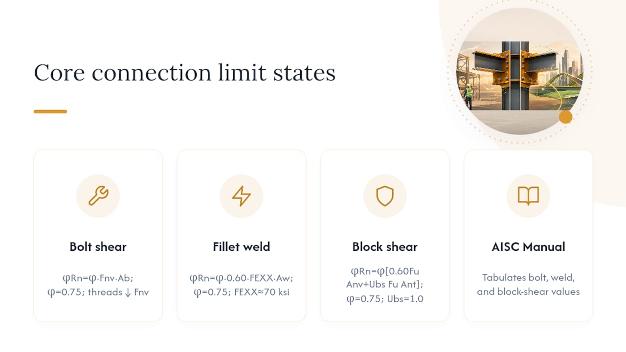
Bolt shear (AISC 360 Section J3.6):
φRn = φ × Fnv × Ab
Where φ = 0.75, Fnv is the nominal shear stress (tabulated in AISC 360 Table J3.2), and Ab is the gross bolt cross-sectional area. For threads included in the shear plane, use the reduced Fnv value.
Fillet weld throat capacity (AISC 360 Section J2.4):
φRn = φ × 0.60 × FEXX × Aw
Where φ = 0.75, FEXX is the electrode classification strength (typically 70 ksi for E70XX), and Aw is the effective throat area (0.707 × weld size × length for a 45° fillet).
Block shear rupture (AISC 360 Section J4.3):
φRn = φ × [0.60 Fu Anv + Ubs Fu Ant] ≤ φ × [0.60 Fy Agv + Ubs Fu Ant]
Where φ = 0.75, Anv and Ant are net areas in shear and tension, Agv is gross shear area, and Ubs = 1.0 for uniform tension stress.
The AISC Steel Construction Manual tabulates bolt capacities, weld strengths, and block shear values for standard configurations, significantly reducing hand-calculation time.
For AISC connections, CalcSteel’s documentation compiles these limit states alongside weld equations and bolt grade comparisons, which is useful for cross-referencing formula callouts and reviewing international code differences.
Pro Tip: Bolt group eccentricity is the most frequently omitted check in shear tab and angle connection designs. Always resolve the eccentric shear into a direct shear component and a moment component, then use the Instantaneous Center of Rotation (ICR) method or AISC Manual Table 7-6 to find the critical bolt force.
Common connection types and the checks that typically control them
Matching a connection type to its governing limit states before starting calculations saves significant time and prevents the common error of running every check at equal depth.
- Shear tab (single plate): Bolt shear and bearing typically control for short connections. Block shear on the plate governs when edge distances are tight. Weld shear at the supporting member controls when the plate is thin. Eccentricity between the bolt group centroid and the weld line must be accounted for.
- Single and double angle: Bolt shear and angle leg bending control for bolted angles. For welded angles, weld shear along the outstanding leg governs. Prying action on the outstanding leg is frequently underestimated and must be checked per AISC Manual Part 9.
- Seated connection: Bearing on the seat angle and bolt shear in the seat typically control. Stiffened seats require web crippling and local web yielding checks on the supported beam.
- Extended end plate (moment): Bolt tension and prying action control the tension flange region. Plate bending, column flange bending, and panel zone shear must all be checked. AISC Design Guide 4 and Design Guide 16 provide prequalified configurations for seismic and non-seismic applications.
- Flange plate (moment): Plate net section fracture and weld shear at the flange plate-to-column interface typically govern. Block shear on the plate is also a common controlling state.
- Welded flange (moment): CJP weld tension at the beam tension flange controls. Demand-critical weld requirements under AISC 341 apply in seismic zones; CVN toughness requirements for the weld metal must be specified.
- Gusset/bracing connections: Block shear on the gusset plate and bolt shear in the brace-to-gusset interface typically govern. The Uniform Force Method (AISC Manual Part 13) distributes forces to the beam and column interfaces without introducing moments.
- HSS connections: Branch member punching shear and chord wall plastification control for HSS-to-HSS joints. AISC 360 Chapter K provides the governing expressions; wall slenderness limits are critical.
- Base plates: Anchor rod tension and concrete bearing pressure control for moment base plates. Plate bending under the compression block governs plate thickness. ACI 318 Appendix D (or Chapter 17 in ACI 318-19) governs anchor design.
For a detailed comparison of bolted and welded connections and their practical differences, Stellar Structures’ published guidance covers the key tradeoffs engineers face in practice.
Worked example: bolted shear tab connection
Given: A W18×50 beam frames into a W14×90 column web. Factored shear demand Vu = 65 kips. Connection: 3/8-in. A36 shear tab, three ¾-in. diameter ASTM F3125 Grade A325 bolts in standard holes, nominal bolt spacing, and appropriate edge distance per code. LRFD design per AISC 360.
Step 1: Bolt shear capacity
From AISC 360 Table J3.2, Fnv = 54 ksi (threads excluded from shear plane, N-type).
Ab = π(0.75)²/4 = 0.4418 in²
φRn per bolt = 0.75 × 54 × 0.4418 = 17.9 kips
Total φRn (3 bolts) = 3 × 17.9 = 53.7 kips
Note: With Vu = 65 kips > 53.7 kips, bolt shear is inadequate. Increase to four bolts or upgrade to A490.
Revised: 4 bolts, A490 (Fnv = 68 ksi)
φRn per bolt = 0.75 × 68 × 0.4418 = 22.5 kips
Total φRn = 4 × 22.5 = 90.0 kips > 65 kips ✓
Step 2: Bolt bearing on plate
φRn per bolt = 0.75 × 2.4 × Fu × d × t = 0.75 × 2.4 × 58 × 0.75 × 0.375 = 29.3 kips/bolt
Total = 4 × 29.3 = 117.2 kips > 65 kips ✓
Step 3: Plate shear yielding and rupture
Plate height = 4 × 3 + 2 × 1.5 = 15 in.
φVn (yielding) = 0.90 × 0.60 × 36 × 15 × 0.375 = 109.4 kips > 65 kips ✓
Anv = (15 − 4 × 0.875) × 0.375 = 4.313 in²
φVn (rupture) = 0.75 × 0.60 × 58 × 4.313 = 112.9 kips > 65 kips ✓
Step 4: Block shear rupture
Agv = (15 − 1.5) × 0.375 = 5.063 in²; Anv = (13.5 − 3.5 × 0.875) × 0.375 = 3.922 in²
Ant = (1.5 − 0.5 × 0.875) × 0.375 = 0.398 in²; Ubs = 1.0
φRn = 0.75 × (0.60 × 58 × 3.922 + 1.0 × 58 × 0.398) = 119.0 kips > 65 kips ✓
Result: With four ¾-in. A490 bolts and a 3/8-in. × 15-in. A36 shear tab, all limit states pass. Bolt shear governed the initial three-bolt layout; the revised four-bolt configuration provides a utilization ratio of 65/90 = 0.72 on the controlling limit state.
Refer to AISC Manual Tables 10-1 through 10-9 for tabulated shear tab capacities that confirm these results without full hand calculation.
Which tools should you use for connection design calculations?
The right tool depends on the complexity of the connection, the required output format, and the project’s inspection and permitting requirements.
Rule of thumb: Hand calculations for quick verification; online calculators for routine shop designs; full connection software for complex nodes, seismic detailing, fatigue, or FEA-level checks.
| Tool | Best For | FEA/CAD Interoperability | Compliance-Ready Output | Learning Curve / License |
|---|---|---|---|---|
| Hand calc (AISC Manual) | Quick checks, peer review, education | None | Engineer-stamped PDF | Minimal / free (manual cost) |
| SkyCiv Connection Calculator | Routine bolted/welded connections, AISC 360 code reports | Limited (model import) | Automated AISC code report | Low / subscription |
| IDEA StatiCa | Complex nodes, seismic, fatigue, FEA verification | Strong (Revit, Tekla, SAP2000, ETABS) | Detailed FEA + code report | Moderate-high / commercial |
| CalcSteel | AISC formula reference, quick parametric checks | Limited | Calculation output | Low / web-based |
| SDS2 / IntelliConnect | Fabrication-ready detailing, shop drawing automation | Strong (model-native) | Shop drawings, CNC data | High / commercial |
SkyCiv Connection Calculator generates AISC 360-compliant calculation reports for standard bolted and welded connections, making it practical for routine shop designs where a documented code check is required without full FEA.
IDEA StatiCa uses a Component-Based Finite Element Method (CBFEM) to analyze connection behavior at the stress level, which is particularly valuable for non-standard geometries, seismic demand-critical connections, and fatigue-sensitive joints. Its direct links to Tekla Structures, Revit, SAP2000, and ETABS reduce manual force extraction errors.
CalcSteel provides a web-based reference for AISC connection formulas and bolt/weld parameters, useful for checking hand calculations or reviewing limit-state expressions quickly.
SDS2 and IntelliConnect (Prota Software) automate connection application and detailing within the structural model, with IntelliConnect supporting automated creation across multiple common connection categories. These tools reduce manual corrections and accelerate shop drawing production for fabricators.
For engineers using STAAD.Pro for analysis, exporting member forces into a dedicated connection calculator is the standard workflow for maintaining traceability between the analysis model and the connection design.
- Hand calculations: Full transparency, no license cost, best for peer review and education. Time-intensive for complex geometries.
- Online calculators (SkyCiv, CalcSteel): Fast, code-referenced outputs. Limited to standard configurations; not suitable for irregular nodes.
- Full FEA software (IDEA StatiCa): Handles any geometry, produces detailed stress outputs. Higher cost and learning curve; output requires engineering interpretation.
- Integrated detailing (SDS2/IntelliConnect): Best for fabrication productivity. Less suited to standalone design verification without a full model.
Export PDF calculation reports for permitting submissions and DXF/CNC files for fabrication. Always retain the input file alongside the output report so assumptions can be audited.
Shop vs. field: fabrication, QA, and inspection guidance
Push critical, high-quality work to the shop whenever geometry permits. Shop welding offers better quality control, controlled preheat conditions, and easier inspector access than field work. Field connections are typically bolted to reduce schedule risk and minimize the need for field welding inspection.
Practical coordination items that prevent rework:
- Mill and fit-up tolerances: AISC Code of Standard Practice Section 6 defines acceptable mill tolerances for member camber and sweep. Connection plates must accommodate these tolerances; design for ±1/16-in. fit-up variation at field splices.
- Weld access holes: Size and finish per AISC 360 Section J1.6. Undersized or rough access holes are a leading cause of weld defects at moment connection flanges.
- Preheat and hydrogen control: AWS D1.1 Table 4.5 specifies minimum preheat temperatures by base metal thickness and carbon equivalent. Field welding in cold weather without verified preheat is a significant quality risk.
- DTI and TC bolts: Direct Tension Indicators (DTIs) and Tension Control (TC) bolts provide verifiable pretension without torque wrench calibration. Specify these where inspection capacity is limited or where the inspector cannot observe the full installation sequence.
- Slip-critical joint inspection: AISC Research Council on Structural Connections (RCSC) Specification governs pretensioning methods. Confirm that the faying surface condition matches the specified Class A or Class B slip coefficient.
- Fatigue and cyclic loading: For connections subject to cyclic loading, classify the detail per AISC 360 Appendix 3 (fatigue) and AWS D1.1 fatigue provisions. Pretensioned slip-critical bolts can outperform welds in fatigue when properly installed and inspected, particularly where weld quality cannot be fully verified in the field.
- Corrosion protection: Hot-dip galvanizing, metallizing, or paint systems must be specified before fabrication. Galvanized faying surfaces require a Class D slip coefficient adjustment for slip-critical joints. Specify coating thickness and holiday testing requirements on the connection detail drawings.
- Fire resistance: Connections in fire-rated assemblies require intumescent coating or encasement. Exposed moment connection bolts and welds must be included in the fire protection scope; omitting them is a common coordination gap between structural and architectural drawings.
Pro Tip: Specify pretensioned bolts (snug-tight is not sufficient for slip-critical joints) and note the inspection method on the connection detail. A drawing note that reads “pretensioned per RCSC, TC bolt method” gives the inspector a clear, verifiable acceptance criterion without requiring a torque wrench on site.
For a broader view of how shop-vs-field decisions affect project cost and schedule, value engineering guidance for steel structures provides constructability tradeoffs that directly influence connection detailing choices.
What your calculation report and shop drawings must include
A complete connection design deliverable contains three layers: the calculation package, the shop drawings, and the QC/inspection requirements. Missing any layer creates gaps that fabricators and inspectors cannot resolve without returning to the engineer of record.
Calculation package:
- Assumptions and load summary (factored demands per load combination, source analysis model reference)
- Connection demand summary (shear, axial, moment at each connection)
- Detailed limit-state checks for every governing failure mode, with formula references to AISC 360 section numbers
- Bolt schedule (diameter, grade, pretension requirement, hole type, installation method)
- Weld schedule (type, size, length, electrode classification, AWS D1.1 prequalified or qualified procedure reference)
- Material specifications (plate grade, bolt grade, weld consumable)
Shop drawings:
- Plan, elevation, and section views with all dimensions, hole locations, and edge distances
- Weld symbols per AWS A2.4
- Hole type designation (standard, oversized, short-slot, long-slot) and any special surface preparation notes
- Erection marks cross-referenced to the erection plan
QC and inspection requirements:
- Bolt pretension acceptance criteria (DTI gap, TC bolt spline break, or calibrated wrench torque)
- Weld inspection scope: visual inspection (all welds), ultrasonic testing (UT) or magnetic particle testing (MT) for CJP welds in demand-critical or fatigue-sensitive locations
- Grout and anchor installation acceptance criteria for base plates (grout type, minimum compressive strength, curing period)
- Non-destructive testing (NDT) requirements referenced to AWS D1.1 Table 8.1 acceptance criteria
For projects requiring civil and structural design checks. A complete documentation package is the baseline for any third-party review or authority submission.
A practitioner’s perspective on structuring connection design work
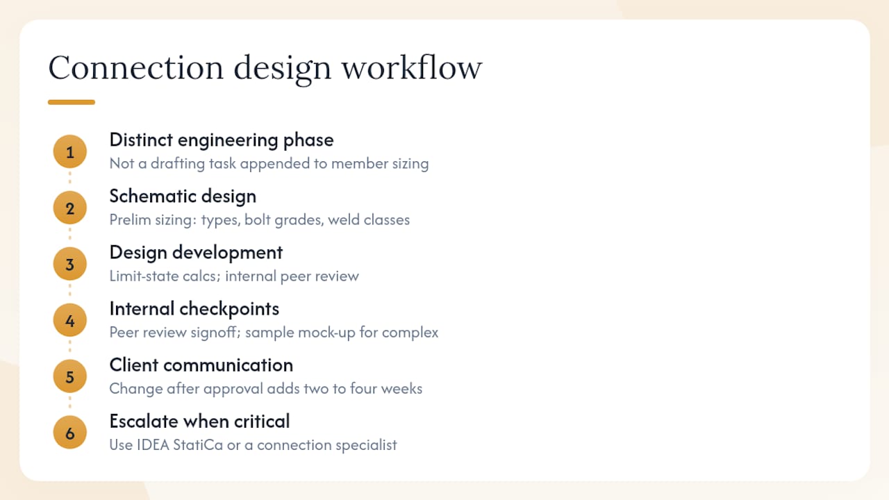
The most effective approach to connection design is to treat it as a distinct engineering phase, not a drafting task appended to member sizing. Connections that are sized concurrently with the framing system, rather than after the structural model is finalized, consistently produce better constructability outcomes and fewer RFIs during fabrication.
A typical firm workflow begins with preliminary connection sizing during schematic design, where the engineer of record establishes connection types, bolt grades, and weld classifications based on anticipated demands. This early commitment constrains the detailer and fabricator to a coherent system rather than leaving connection selection to the shop. At the design development stage, detailed limit-state calculations are completed and peer-reviewed internally before issuing for fabrication. The peer reviewer specifically checks eccentricity assumptions, block shear paths, and weld access hole geometry, which are the three areas where errors most frequently survive initial design.
Two internal checkpoints have proven most effective: a peer review signoff before the calculation package is issued for fabrication, and a fabrication shop sample mock-up for complex moment connections or non-standard geometries. The mock-up review catches fit-up issues and weld access problems that no drawing review will reveal. Client communication at this stage focuses on lead time implications: a connection type change after shop drawings are approved typically adds two to four weeks to the fabrication schedule.
For complex nodes, seismic demand-critical connections, or connections with significant fatigue demands, escalating to IDEA StatiCa or a connection specialist is the standard practice, not an exception. The cost of a specialist review is negligible relative to the cost of a field correction or a structural failure investigation.
Stellar Structures provides code-compliant connection design and documentation
Structural engineers and developers working on building projects in Singapore can engage Stellar Structures for complete connection design packages: AISC-aligned or SS EN-aligned limit-state calculations, bolt and weld schedules, shop drawing production, fabrication QC checklists, and on-site erection supervision. The firm’s structural team handles the full sequence from load extraction through authority submission, so the calculation package, shop drawings, and inspection records are coordinated from a single point of accountability.

For projects requiring integrated design and engineering support, Stellar Structures manages the coordination between structural design, detailing, and authority submission so that connection design decisions are traceable through to the final permitting record. Contact Stellar Structures to discuss your project scope and receive a fee proposal for connection design services.
Sources
Confirm the edition and errata status of every standard before citing it in a calculation package. Jurisdictions adopt specific code cycles, and a mismatch between the design guide edition and the adopted AISC 360 version can introduce inconsistencies in resistance factors and limit-state expressions.
Recommended
- Essential Guide to Steel Structure: Types, Benefits, and Applications
- Steel Structure Connections: Welded and Bolted Connection Design and Their Differences – Stellar Structures
- Steel Structure Analysis and Design Using STAAD Pro – Stellar Structures
- The Ultimate Guide to Value Engineering Steel Structures: Design, Cost, & LEED